Neither the commissions in Germany nor the Chemistry Research Board in Great Britain examining the causes of the 1921 Oppau explosion apparently had any “mining engineers” – of which there would have been many veterans of World War I who would have been quite knowledgeable in Germany as well as France and Great Britain – who would seemingly have been able to shed a lot of light on the subject of explosive cratering.
Following a war in which British, French & German forces had over and over employed underground mines to blast numerous large craters on the Western Front, it is quite curious that no mining engineer who should have known better ever publicly even suggested that underground mines could have caused the 1921 Oppau explosion(s). But the mining engineers of the time never even questioned (at least not publicly) the general assumption in all the reporting on the Oppau explosion that INDEED an aboveground warehouse explosion could blast a large crater. The fact that NONE of these explosives experts stepped forward to publicly criticize the “official” theory that the 1921 Oppau catastrophe including the massive crater was caused by the explosion of a pile of ASN, whether 450 tons or 4500 tons, stored in an aboveground silo, just shows that “old experts” were no better than “new experts” when it comes to challenging “official” stories!
Although the Oppau crater was larger than even the largest World War I craters, the one World War I crater that most stands out as the most interesting in terms of comparison to the Oppau crater is the Lochnagar crater.[1]
Looking at images of the Lochnagar crater gives us some sense that this crater was not unlike the Oppau crater except that it did not fill up with groundwater like the Oppau crater. Indeed, the two craters are similar enough that it is hard to imagine that one was supposedly blasted by a massive aboveground explosion (Oppau) and the other supposedly blasted by a massive underground explosion (Lochnagar)! Curiously, Lochnagar Crater was also blasted by TWO consecutive explosions rather than two simultaneous explosions, much as Guckel and Hecker had suggested for Oppau crater, athough Lochnagar crater ended up being far more circular in shape than Oppau, perhaps due to the shorter distance between the two explosion centers.

Troops Passing Lochnagar Crater, October 1916[2]

Lochnagar Crater, August 1916[3]

Burial Mound in the Bottom of Lochnagar Crater, September 1917

Lochnagar Mine[4]

But the Lochnagar crater is also quite useful for our purposes because it just happens to be the best preserved today of all the Western Front craters, giving an even better sense of just how big it was in terms of both diameter and depth.[5]

The failure to see any connection – both then and now – between the explosive craters of the Western Front and the Oppau crater was certainly NOT because of any lack of familiarity with World War I battlefield imagery. Indeed, several reporters commented that their first thought upon seeing the site of the Oppau explosion was that it reminded them of a World War I battlefield. The Associated Press release on the day of the blast announced “Berlin dispatches describe the scene of the blast and adjacent territory as a veritable battlefield, covered by wreckage and mangled bodies.”[6]

An article tiled “Oppau A New Ypres” in the 26 September 1921 edition of the London Daily Mirror announced the showing in a large number of cinemas of a British Pathé film amply confirming “the reports of the appalling extent of the disaster”:
Oppau has become a German Ypres. The once flourishing town surrounding the chemical works is now seen to be a mere jungle of twisted girders and a waste of ruined masonry. The huge crater, rapidly filling with water, that marks the site of the factory, is the centre of a vast circle of wreckage, extending for miles in every direction. One mass of tangled machinery, estimated to weigh twenty tons, was thrown several hundreds of yards through the air.[7]

The Pathé film is currently available on YouTube but unfortunately the film does not really show the crater.[8]
Although no mining engineer publicly questioned the “official” story that the explosion of hundreds or thousands of tons of fertilizer in an aboveground warehouse was responsible for blasting the huge Oppau crater, we have already noted some inklings of doubt. For example, Sir Richard Threlfall, speaking in Great Britain for the Chemistry Research Board of the Department of Scientific and Industrial Research (hereafter CRB), did consider the possibility “that a quantity of 50 to 100 tons of high explosive was concealed deliberately under the store, and that it was the explosion of this material which led to the disaster.[9] Although, Threlfall does not mention the crater, at least some members of the board should have known that the explosion of “a quantity of 50 to 100 tons of high explosive” “under the store” could more understandably have blasted such a huge crater that the “official” story. Even if the board had to dismiss Threlfall’s idea as a more “extreme” improbability, the fact that they even raised the possibility suggests the board knew there was plenty wrong with what would eventually be accepted as the “official” explanation.
For his part, Hermann Kast states in the 1925/26 report that the Oppau explosion would have required “several hundred tons of explosive” [mehreren 100 t Sprengstoff] “under the fertilizer salt” but again does not refer to the effect this might have on a crater and suggests “under the fertilizer salt” would be no different than “in the passageway of silo 110.”
Finally, the thought, which is in and of itself absurd, should be mentioned that under the fertilizer salt or in the passageway of silo 110 munitions [Munition] had been kept for criminal domestic or extra-political purposes and which would have exploded by accident. These munitions, if they alone had caused the explosion, would have to have been present in very large quantities, several hundred tons of explosives [mehreren 100 t Sprengstoff], or, if it had only acted as an initial detonator, it would have had to have been in close contact with the fertilizer salt, i.e., have been hidden in it have been. In the first case, however, it could not have been accommodated in the walkway without being noticed by employees or officials of the factory; in the latter case, it would not have caused the great destruction and at most had the same effect as that which has been proven directly in the explosive shots used in salt piles.[10]
As far as I have discovered, there was really only one “expert” who seriously raised the issue that only an underground explosion could have blasted the Oppau crater and that was in an article titled “Evidence from the Photographs” and subtitled “Editorial Comment” with no author listed in the November 2, 1921, issue of the American journal Chemical and Metallurgical Engineering. [11] One imagines that whether or not this “Editorial Comment” was written by the journal’s editor, H. C. Parmelee, it certainly would have been approved by Parmelee. Suggestive that Parmelee was involved in the editorial is that he was similarly quite publicly critical of the U.S. Navy’s investigation of the Lake Denmark naval ammunition depot disaster in July 1926.[12] Whoever the author was, to judge by the quality of the analysis, one would have to conclude that the author qualified as an explosives “expert.”


The anonymous “editor” would seemingly have dismissed the arguments that the fertilizer salt in silo 110, whatever the % composition of AN and AS, would have been explosive. Indeed, he wrote
neither ammonium nitrate nor the mixed salts (ammonium sulphate-ammonium nitrate) are usually regarded as explosive. Pure nitrate must be highly compressed and slightly heated before it can be detonated by a blasting cap. The commercial salt cakes very easily, and it has been common practice to break large masses by dynamite when necessary to move it. Consequently it is fairly insensible to detonation. Intimately mixed with nitroglycerine, powdered aluminum or TNT, it was used extensively during the war as a high explosive, the two latter being commonly known as amonal [sic] and amatol.[“Evidence for the Photographs” 821.[/ref]
The “editor” suggested that an aboveground explosion could have blasted the Oppau crater but it would have required “thousands of tons of the most violent explosive” and elsewhere wrote the aerial photo “shows a crater that would be expected from no less than thousands of tons of TNT.” Thus, there would have had to have been some unreported explosive other than ASN or AN with an explosive yield equivalent to thousands of tons of TNT in silo 110 to have blasted the Oppau crater.
Furthermore, the “editor” suggested that the explosives were likely UNDER silo 110, noting that the aerial photo showed evidence that
the crater was excavated by a shock whose main effect was expended in a vertical cone. Note the way the upper ends of the walls of the storage buildings are trimmed off, also the way the near corner of the building at the left is shot away, leaving spindly steel columns standing near by.
The “editor” concluded:
By the effects, one is tempted to suppose that it was some CELLARS full of this stuff [i.e., ammonal or amatol] which let go or perhaps even some forgotten MINES prepared for the day when the Allied troops would appear along the Rhine![13]
And yet even though it had been only 4-5 years since the massive explosive cratering on the Western Front in World War, it is telling that this was the entire extent (as far as I have found) of questioning the idea that a large warehouse could have blasted a large crater in 1921 among “experts” who might at least have questioned whether such a thing was possible and might have seriously raised the possibility that an underground explosion could have been involved in Oppau.
Kast’s Spreng- und Zündstoffe (1921)
Hermann Kast was certainly familiar with the literature on underground mines having just recently published a book Spreng- und Zündstoffe (“Explosives and incendiary materials”). Indeed, the book came out in the same year as the Oppau blast – 1921!

Before we try to make sense of what Kast wrote in his 1925/26 report to demonstrate than an aboveground explosion could have blasted the Oppau crater, it seems a good idea to check out what he wrote about craters in this 1921 textbook that came out before anyone had ever conceived that a storehouse explosion could blast such a large crater.

Kast began his introduction to explosive cratering analysis with the crater diagram in Figure 4, where he labeled the point M the center of the explosive, r the radius of the crater opening at the pre-explosion surface, and l “the line of least resistance [LLR],” i.e., the perpendicular distance between the center of the charge and the pre-explosion surface. With that, Kast laid down the basic formula (Minenregel) for calculating the weight of a mine charge L necessary to blast what was called at the time an “ordinary mine” – Kast called this a ”normal mine” – that blasts a crater in which r = l
L = m · l3 (1)
where m is an empirical coefficient depending on the particular explosive, the particular type of earth, and the units used.
This formula for an “ordinary mine” went back well over 200 years to at least the time of the Marquis of Vauban when “explosive experts” first realized that the proper mine charge weight L for an “ordinary mine” was directly proportional to the cube of the line of least resistance l.[14]
Kast claimed:
The formula is derived from the assumption that the detonation gases expand spherically and that thus, in order to excavate the funnel shown in Fig. 4, the radius [of the sphere of expanding detonation gases] must be at least equal to the line of least resistance.
Kast’s claim about the formula’s derivation was not really true because the Minenregel existed for decades before Bernard Forest de Bélidor proposed the idea of a globe de compression (that Kast is seemingly referencing with his ideas about a sphere of expanding detonation gases) in a manuscript he completed in 1729 and the Minenregel was shown by numerous scholars over the previous 200 years to still hold true for every attempt to improve upon the Minenregel on empirical or theoretical grounds as long as l = r.
Interestingly, Kast notes for this “ordinary mine” that “the earth is lifted by the explosion, but falls back in part, whereby it fills the raised funnel again to about 1/3 its depth.” I believe what Kast was saying here is that the depth of the crater for an “ordinary mine” after the earth in part has fallen back – what in modern parlance is called the “apparent crater depth” – is equal to 1/3 of the LLR. If so, what Kast was saying was not new. Indeed, it is exactly what Dambrun stated back in 1871 as “well established by experience with respect to the depth of the funnel, namely, that for ordinary mine chambers it is equal to 0.33 H,” where H was the symbol Dambrun used to represent the LLR (where Kast had used l). [15] (Note, however, that Kast who appears to depict an “ordinary mine” (r = l) in Fig. 4 mistakenly depicts an apparent crater depth approximately 1.33 H, not .33 H!)
Kast in his 1921 book recognized that not all mines are “ordinary mines.” He states mines can be “overloaded” (r/l > 1) or “underloaded” (r/l < 1). He also acknowledged that “in reality, the calculation is much more complicated” depending on, among other things, “the depth at which the charge is located” by which he is likely referring to the fact that all charge calculations proposed since Bélidor can be expressed as various functions of r/l, a ratio for which mining engineers have long used the symbol n.
Actually, Kast exaggerated here because, “in reality,” the calculations employed by mining engineers for “ordinary”, “overloaded” and “underloaded” mines were NOT “much more complicated.” Indeed, the single formula used by both the French and British militaries in World War I for “overloaded” and “underloaded” mines was only a slight variation of the formula for the proper mine charge weight (L) for an “ordinary mine.” Indeed, one equation covered all three types of mines:
L = m · l3 [(√(1+n2) – .41]3
where n = r/l.
Solving for the “ordinary mine” (n = 1), we get the exact formula Kast reported (L = m · l3) as the Minenregel.
This formula actually dates back to the 1860s and the work of Dambrun and Ricour.[16]

Ricour premised his “nouvelle théorie des mines” on the idea that when the center of a charge of gunpowder is detonated at point O in a homogeneous and compressible soil at a depth of OP below the plane TT (Fig. 12), the gases produced by the combustion of the gunpowder presses back the soil in all directions creating an inner spherical void. This void is traditionally called the chambre but Ricour preferred to designate more specifically as the sphère de compression. He points out that even a weak load can produce a relatively large chamber, noting 1 kg of powder can create a chamber more than 1 meter in diameter.[17]

Referring to the inner circle labelled AB and the outer circle A’B’ (the rightmost B should actually be B’) in Figure 15, Ricour continued:
Let AB be the void produced by the powder charge; all around the land will have been pushed back, and at a certain distance the interior action will have been nil. There will therefore exist a sphere A’B’ concentric with the sphere of compression AB, which will be such that all the external ground will not have been subjected to the effect of the gases produced by the ignition of the powder [Fig. 15]. Their action from the center ceases on its surface; for this reason we will call this sphere “maximum sphere of action”, or simply “sphere of action.”[18]
Ricour stated he felt a priori there must be a relationship between the radii of the sphere of action and the sphere of compression.[19]
Ricour first developed an equation for the radius of the sphere of compression for a given charge c and terrain based on Mariotte’s Law (known in English as Boyle’s Law) where the product of pressure p and volume v is constant for a given mass of confined gas as long as the temperature is constant. Assuming the temperature remains constant, Ricour thus asserted the product of initial pressure (pi) and volume (vi) will equal the product of final pressure (pf) and volume (vf).
pivi = pfvf
Ricour calculated initial volume as the size of the charge c divided by its density D
vi = c/D
and the final volume as the volume of the maximum sphere of compression with radius ρ as
vf = 4/3 π ρ3
Labelling initial pressure T that he asserts is a constant (for the particular explosive, i.e., gunpowder) and final pressure as P that he also asserts is a constant for the resistance that the particular terrain offers per unit area to compression, and plugging in each of these values into the equation pivi = pfvf he wrote
4/3 π ρ3 P = (c/D) T,
or
ρ3 = c (3T/4πDP) (1)
This showed that the cubes of the radius of compression ρ is proportional to the charge c since the factor 3T/4πDP is constant for the same milieu. Ricour offered experimental evidence from three test mines that demonstrated the ratio ρ3/c is a constant.[20]
If the charge is low relative to the depth OP – so that the sphere of action does not extend to the plane TT – there are no external effects.[21] The maximum camouflet occurs when the sphere of action is tangent to the surface TT and produces no external effect. Ricour reported that
Experience has shown that, when a charge of powder c’ produces an ordinary mine chamber in a medium at depth H, at depth h = 1.75H we have the maximum camouflet in the same terrain. [22]
Substituting h/1.75 for H in the equation that all miners use for calculating the charge for an ordinary mine
c’ = g H3,
Ricour derives the equation for the charge of a maximum camouflet
c’ = g (h3/1.753) (2)
where h represents both the line of least resistance as well as the radius of the sphere of action for the charge c’.[23]
Ricour then used equations (1) and (2) to solve for the ratio of the radius of the sphere of compression ρ to the radius of the sphere of action h represented by the symbol α which is a constant for the same earth and powder:
α = ρ/h = 1/1.75 ∛(3gT/4πDP)
or
ρ = αh (3)
Equation (3) shows that the radius of the sphere of compression is proportional to the radius of the sphere of action and, for a maximum camouflet, the radius of the sphere of compression is proportional to the line of least resistance.[24]
As to what happens when the charge is increased beyond that which will produce a maximum camouflet, Ricour described the two phases in the charge combustion of a mine chamber.

In the first phase, the first part of the powder burns, compressing the earth in all directions forming the maximum sphere of compression Op (Fig. 17). On the surface, one feels a slight tremor and the ground rises a little above the powder.[25]

In the second phase, the powder not yet burned is surrounded on all sides by the first gases produced and the combustion is very rapid, almost instantaneous. All forces are normal to the inner surface of the void and the truncated cone A’pB’BA is removed (Fig. 18). The projection gets weaker as we get closer to the generatrices AA’ and BB’ and the projection will be zero at the funnel perimeter. On the surface one sees this as, almost immediately after the ground rises a little, the projection takes place with the central parts of the funnel lauched the highest and, at the edges of the funnel, the clods of earth are barely turned over.[26]
Ricour hypothesizes that the length of rupture line (ligne de rupture) BB’ obviously depends on the powder charge, thus can be expressed as
BB’ = F(c’).[27]
Since neither α and F(c’) are known, Ricour uses two equations for the radius of the sphere of action – one for a maximum camouflet and another for an ordinary mine – to solve for them.
For the ordinary mine (Fig. 18), the radius of the sphere of action can be expressed as the sum of the radius of the sphere of compression plus the length of the rupture line by the equation
OB = OB’ + B’B.
Knowing that for an ordinary mine OP = PB = H and thus OB = H √2 and that OB’ = Op = αH and B’B = F(c’), by substitution, we have the 1st equation
H √2 = αH + F(c’).[28]
For the maximum camouflet (Fig. 17), the radius of the sphere of action can similarly be expressed by the equation
OP = Op + pP
Knowing from experience that OP = 1.71 H, Op = α x OP, and pP = F(c’), we have the 2nd equation
1.71 H = 1.71 α H + F(c’)
[29]Solving these two equations for α and F(c’), Ricour found
α = 0.41
which he says is nothing but √2 – 1, and thus
F(c’) = H.
Thus the length of the rupture line is equal to the depth H as which the load c’ acts as an ordinary mine. Knowing that c’ = g H3, we can write
F(c’) = ∛(c’/g)
with g being a coefficient dependent on the nature of the ground and the quality of the powder.[30]
To write the general equation for a powder charge producing any funnel A’pB’BA in terms of the funnel radius (r) and line of least resistance (h), Ricour noted since OPB is a right triangle
OB2 = OP2 + PB2 = h2 + r2
Since OB = OB’ + BB’ = Op + BB’, and substituting BB’ = ∛(c’/g) and Op = 0.41 h,
r2 + h2 = (0,41 h + ∛(c’/g))2,
which, substituting n = r/h and solving for c’, Ricour derived the general equation for mines
c’ = g h3 (√(1 + n2) – 0,41)3
or
c’ = c (√(1 + n2) – 0,41)3
that he noted was identical to the equation that Dambrun had earlier proposed on empirical grounds.[31]
Apparent Crater Depth
Dambrun took his cratering analysis one step farther to come up with an empirical formula for calculating apparent crater depth.

We have already mentioned that Kast stated in his 1921 book what Dambrun had fifty years earlier written was “well established by experience” about the profondeur de l’entonnoir – representing what in modern terms we would call the “apparent crater depth,” i.e., the perpendicular distance from the pre-blast surface of the earth to the lowest part of the post-blast crater – of an ordinary mine equal to 1/3 of the LLR. Dambrun noted, in addition, that “according to Lebrun, to obtain [a crater depth] equal to h, the load must act like an overloaded furnace for which n = 2,” where h represents the line of least resistance.[32]
In the published 1873 edition of his memoir, Dambrun proposed two formulae for apparent crater depth that he said corresponded to these “two facts.”
The depth of the funnel below the natural ground is fairly well represented by the two empirical relations
p = 0.80 (R – h) or p = 1/3 h (2n – 1).[33]
Dambrun supported his two equations noting the close correspondence between the results of the two equations with depths determined from test mines in the following table.[34]

It is not clear why Dambrun presented two such different equations except that both happened to produce similar results in the range 1 <= n <= 3. However, the second formula seems to be more in line with, not just Dambrun’s “facts,” but also Pasley’s comments in 1817 where he stated for a “one lined crater” (n = .5) “the earth is either merely agitated, or only raised a very little higher than the surface, and then falls down again into its original position nearly” suggesting p = 0, consistent with the 2nd but not 1st equation. It seems that Dambrun might have also had this “fact” in mind with his 2nd equation although he does not mention it. [35]
By the time Hermann Kast was publishing his 1925/26 report on the Oppau explosion, the British War Office had already published what was the most thorough statement to date on explosive cratering, Military Engineering, Vol. IV: Demolitions and Mining (1923) that showed exactly how to calculate what kind of explosion blasted the huge Oppau crater.[36]

As the War Office stated in the 1923 manual, the war on the Western Front 1914-18 had given both the Allies and the Central Powers a great deal of time to perfect their formula for mine warfare.
The long period of position warfare which obtained on the Western front during the War of 1914-1919, produced conditions which, up till then, had been associated only with fortress warfare…A deadlock had been reached, in which many of the features peculiar to siege warfare were reproduced on a vast scale. [37]

The 1923 British military manual in Chapter XIII “Calculation of Charges and their Effects in Mine Warfare” covered much the same ground as Ricour, beginning with examining the explosion of “concentrated charge” (marked O in P. 73, Fig. 1)
buried in homogeneous soil at such a depth that its action cannot reach the surface. A spherical chamber of compression V will be formed by the expanding gases, and in the earth surrounding this chamber compressive stresses will be set up, the limit of which are approximately defined in the section by the circle HKL.[38]
The 1923 British military manual contrasted the explosion of this deeply buried charge with “the case in which the charge is sufficiently near the surface for the effects of the explosion to reach it (Pl. 73, Fig. 2)”:
A chamber of compression will be formed as before, and then the explosive force acting along the line of least resistance OA, which, except in cases where the surface of the ground departs considerably from the horizontal, corresponds with the depth of the charge, will break through to the surface forming a crater circular in plan and of radius AB. [39]
The manual defined the terms that had been used for over a hundred years in charge calculations (that will also be useful for analyzing the Oppau crater):
The ratio AB/OA or radius of crater/L.L.R. is called the index of a mine, a numerical factor of first importance in mine calculations. A mine of index = 1, that is to say one in which the radius of the crater formed is equal to L.L.R., is termed a common mine. Mines of index greater than unity are termed overcharged mines, those of less undercharged mines. A charge of the nature [Fig. 1] so small in comparison with the L.L.R. that it will not break the surface, is known as a camouflet. The largest charge that can be blown at a given depth without breaking the surface is termed a maximum camouflet.[40]
Craters are frequently referred to in terms of the ratio of their diameter to the L.L.R., when they are known as one-lined, two-lined, three-lined, &c., according as to whether the length of the diameter is one, two, or three times that of the L.L.R. Thus, the crater formed by a common mine is a two-lined crater.
Immediately outside the circumference of the crater proper, the diameter of which, as already explained, is that of the actual hole formed in the earth measured at surface level, mounds of debris, termed the crater lips (shown by BDF and CEG in section on Pl. 73, Fig. 2), will be thrown up by the explosion. In addition, the ground in the vicinity of the crater edge will be shaken and fissured. Thus, on level ground the zone, within which all personnel will be killed and defences crushed and buried, will be a circle of centre coinciding with that of the crater, but of larger contents. The radius of this circle is termed the radius of destruction.
As in the example of a camouflet … compressive stresses will be set up in the earth surrounding the charge, but in this case the horizontal force will be greater than the vertical force, since a large proportion of the latter will be expended in the formation of the crater. The limit of the extent of these forces is thus approximately defined in section by the ellipse QHKLR (Pl. 73, Fig. 2) with centre at O and major and minor axes OH and OJ.[41]

Employing the symbols used in Fig. 2, Plate 73, the 1923 manual laid down the mine charge calculations based on Dambrun and Ricour employed by the British military:
101. Calculations of charges for mines.
1. The size of charge required to produce a crater of given radius depends on the depth at which it is laid (i.e., the L.L.R.), the nature of the soil, and the nature of explosive used. If—
n = index of the mine (Radius of crater/L.L.R.),
L = depth of charge or L.L.R. in feet,
s = soil factor, a variable dependent on the nature of the soil,
e = explosive factor, a variable dependent on the nature of explosive used,
C = charge of explosive in lbs.,
the relation between these variable is expressed by the equation
C = s/(10e) L3 (√(1+n2) – 0.41)3.
This formula gives accurate results for mines of index ranging between 0 and 3.[42]

The manual provides values for e “in terms of the number of times the power of an explosive exceeds that of Service black gunpowder [e = 1.0] when used in a mine warfare” for a number of “high explosive likely to be used in mine warfare”: ammonal, sabulite, blastine, permite, alumatol, amatol, perdite, donarite, tri-nitro-anisol.[43]

The manual also provides “the average values of s for various soils, obtained experimentally from the results o! a large number of mines” including “made ground” (embankments, &c.) and “virgin soil” (soft sand, hard sand, gravel, sandy loam, clay, blue clay, soft chalk, hard chalk, soft rock, hard rock or masonry).[44]
Where great accuracy is desirable, these figures should only be taken as an initial guide, and the actual value of the soil factor for the particular locality should he ascertained. This can be done by measuring the diameter of crater formed by a given charge at known depth, and solving for s in the formula.[45]
The 1923 British military manual also adopted Dambrun’s 2nd formula for calculating apparent crater depth.
102. Calculation of depth of crater and other surface effects.
1. Depth of crater.—The wedge of earth thrown out by the explosion of a mine will approximate in shape to that of a blunt inverted cone (with apex below the centre of the charge), of which the figure BMNPC (Pl. 73, Fig. 2); but this void is partially filled up again by te earth which falls back under the action of gravity, so that the figure BSCA represents a section of the final shape of the crater. In an undercharged mine the proportion of earth which falls back into the crater is high, and the [155] depth of the crater is thus considerably less than that at which the charge is laid, but as the charge is increased a large proportion of earth is thrown outside the crater, while the void formed below the charge by the chamber of compression is correspondingly greater. As a result, the depth of the crater of a heavily overcharged mine exceeds that of the charge. [154-5]
The depth of the craters of mines of indices between 0.5 and 3 may be calculated from the formula
p = L/3 (2n-1)
where p is the depth of crater in feet.
It will be observed that when n = 2 the depth of the crater is equal to the L.L.R., and that mines of index greater than 2 form craters of depth greater than that of the charge. The depth of the crater of a common mine is L/3. When n = ½, then p = 0, or, in other words, the hole formed by the explosion is completely filled up by the earth which falls back into it. This is found to be approximately correct in practice.[46]

Although the British military manual is dated 1923, it seems likely that the British military were using both the equations for calculating mine charges and apparent crater depth during the war itself. In 1918, H. D. Trounce, formerly Lieutenant in the Royal Engineers of the British Army, presented the same equations (without as thorough detail for determining s and e) in a paper for the U.S. Army Engineer School, acknowledging that he was simply borrowing the formula used by French engineers that had been found to be “very accurate, particularly so for the use of Ammonal [the main explosive used for blasting mines in World War I].”[47] Interestingly, the equation for apparent crater depth p = L/3 (2n-1) will continue to be used in studies for aerial bombardment of World War II as well as studies of underground nuclear explosions of the 1960s, and was even applied to a 1943 study of the Meteor Crater in Arizona.[48]
Forensic Crater Analysis
Since the Oppau crater was larger than any of the World War I craters, you might think that certainly SOMEBODY would have wanted to compare all that “explosive experts” knew about explosive cratering using underground mines with these new revelations about explosive cratering blasted by an aboveground explosion. Surely some mining engineer back in 1921 would have wanted to come up with an estimate of the charge and LLR for the explosion(s) that blasted the Oppau crater(s) – if just for comparison purposes – based on the the best military understanding of military mines?
Indeed, one might wonder how the British Chemistry Research Board could have come up with a number like “50 to 100 tons of high explosives” as the quantity of high explosive that was “concealed deliberately under the store” or how Kast could have come up with “several hundreds of tons of explosive” without doing a cratering calculation, however “improbable” or “absurd” the idea was?
“Explosive experts” in the early 20th century did not typically engage in forensic analysis but military men in Germany, France, Great Britain, the United States, and many other countries had certainly developed the tools for determining the explosive charge and the depth at which the explosives were buried based simply on the ratio of the apparent crater diameter to the apparent crater depth (as well as assumptions about the kind of explosive used and the type of soil). Before we can truly understand how radical Kast’s explanation of the Oppau crater, we should understand how military engineers might have analyzed (if they had actually done so) the Oppau craters using these tools.
As far as I know, no “explosive expert” has ever examined the formula to express the ratio of apparent crater diameter to the apparent crater depth (traditionally represented by the function d/p) as a function of the ratio of the apparent crater radius to the line of least resistance (traditionally represented by the symbol n) using the two Dambrun equations.
Using
p = L/3 (2n -1) (1)
where
p = apparent crater depth
L = line of least resistance
d = apparent crater diameter
r = apparent crater radius
n = r/L
d = 2r
where the particular unit of length does not matter as long as you use the same unit consistently.
From that basic equation (1), we can derive the following alternative equations
d/p = 6n/(2n -1) (2)
n = (d/p)/[2d/p -6)] (3)
L = 3p/(2n-1) (4)
or
L = d – 3p (5)
Table 1 represents the range of possible values of d/p for various values of n.
Table 1
Range of Possible Values of d/p for Various Values of n
|
d/p |
n |
|
3.0 |
undefined |
|
3.5 |
3.5 |
|
4.0 |
2.0 |
|
4.5 |
1.5 |
|
5.0 |
1.25 |
|
5.5 |
1.1 |
|
6.0 |
1.0 |
|
9.0 |
0.75 |
|
undefined |
0.50 |

There is no standard name for the d/p ratio (that we also referred to in Chapter 1 with regard to the OKC crater) but it has been occasionally referred to since at least the 1960s as the “crater aspect ratio” when referring to both explosive and impact craters with crater diameter and depth referenced to the original pre-blast, pre-impact surface.[49]
Lochnagar Crater
To demonstrate how to apply these these equations, we will begin with the example of the 1916 Lochnagar crater and then move onto the 1921 Oppau crater.
The Lochnagar mine tunnel was dug by the British 179th Tunnelling Company through hard chalk south of the village of La Boisselle underneath a German field fortification called the Schwabenhöhe. The tunnel was one of 19 mine tunnels secretly dug under German lines on the British section of the Somme front with the goal of helping the infantry advance on the first day of the Somme.[50]

Plan of the Lochnagar Mine[51]

Aerial view of the site of the Lochnagar mine with marked front lines[52]

Side Elevation Schematic of Lochnagar Mine[53]

British Tunnel in Hard Chalk at La Boisselle[54]
The explosives employed for the Lochnagar mine were divided between two branches, with 24,000 pounds of ammonal in the left branch and 36,000 pounds of ammonal in the longer right branch, for a total of 60,000 pounds of ammonal. As it turned out, the two chambers were not large enough for the charges so the charges ended up overflowing into the branch galleries back to the junction. The two main charges in the chambers were 60 feet apart and 52 feet below the surface.[55]
The Lochnagar double mine was successfully exploded at 7:28 a.m. on 1 July 1916, the first day of the Somme.[57]
On the ground, the shockwaves of the mines were felt far more than heard, there was no bang, either on the Somme or in England as was claimed much later; but 8,000 feet above the battlefield the sound waves reached a pilot who had been warned to keep clear of La Boisselle but turned his machine to observe the detonations of Lochnagar and Y Sap:
… the earth heaved and flashed, a tremendous and magnificent column rose up into the sky. There was an ear-splitting roar, drowning all the guns, flinging the machine sideways in the repercussing air. The earthy column rose, higher and higher to almost four thousand feet. There it hung, or seemed to hang, for a moment in the air, like the silhouette of some great cypress tree, then fell away in a widening cone of dust and debris. A moment later came the second mine. Again the roar, the upflung machine, the strange gaunt silhouette invading the sky. Then the dust cleared and we saw the two white eyes of the craters.
…
An officer of the 3rd Tyneside Scottish, in the second wave to the left of the Lochnagar mine, was exalted:
…we witnessed a most wonderful spectacle. A huge column of chalk was thrown up several hundred feet into the air and came down in a beautiful white cascade.
One of the Grimsby Chums described ‘the whole ground around swaying and rocking as with an earthquake’ and another, who braced his leg against the trench, had it broken by the shock wave. They felt the ground sway three times and saw a crust of earth rise and bursting from it a core of amber:
great pieces of earth as big as coal wagons were blasted skywards to hurtle and roll and then start to scream back all around us. A great geyser of mud, chalk and flame had risen and subsided before our gaze.
Another likened the swaying of the ground to the plate of a weighing machine:
Looking over the parapet, one saw a huge wall rise to some three hundred feet, composed of chalk, mud, dust, timber, etc., with here and there a German. [58]
There were different reports on the size of the Lochnagar crater. In one account, we find “blowing up the German garrison and causing a great crater ninety yards across and seventy feet deep, with lips fifteen feet high.”[59] In another account,
The Lochnagar mine hurled up 84,000 tonnes of earth and chalk and left a crater 220 feet across and 55 feet deep. The debris buried 600 feet of the German front line and the Baden infantry in the dugouts had no chance: some were instantly fragmented, some hurled into the air, crushed, or would die slowly trapped 30 feet underground. [60]
In line with the second description, Simon Jones provided a diagram of a cross section of the Lochnagar crater – the original of which was published in The Work of the Royal Engineers in the European War, 1914-19. Military Mining (Chatham, 1922). [61]

Wikipedia and other online sources have posted a highly similar diagram (see below) from the lochnagarcrater.org website.[62]

The diagrams above depict a cross section of Lochnagar crater that we have already shown in several photos, past and present, above. The diagram also depicts the placement of two mine charges, one of 36,000 lbs of ammonal and the other of 24,000 lbs of ammonal, with the center of each mine chamber about 52 feet below the surface, i.e., LLR equal to 52 feet. The crater has an apparent crater depth of 55 feet and apparent crater diameter 220 feet.

“The Great Mine, La Boisselle”, the Lochnagar Mine depicted by the artist William Orpen in 1917. © IWM (Art.IWM ART 2379)
Quite a few contemporary commentators noted Lochnagar crater for its overwhelming whiteness from all the chalk blasted out of the ground as captured in this painting by William Orpen, “an official war artist” who “saw the mine crater in 1916 while touring the Somme battlefield, collecting subjects for paintings and described a wilderness of chalk dotted with shrapnel.”[63]
Lochnagar Charge Calculations
Unlike the Oppau crater, we have detailed information on how Lochnagar mine was executed, as already summarized. We can first calculate the LLD and charge for the Lochnagar crater with dimensions for apparent crater diameter and depth. Using the apparent crater diameter = 220 feet and apparent crater depth of 55 feet, we calculate
d/p = 220/55 = 4
n = (4)/[2(4) -6)] = 2.0
L (calc.) = 3p/(2n-1) = 3(55)/[2(2.0)-1] = 55 feet
The calculated LLD of 55 ft is thus fairly close to the reported LLD of 52 ft.
Assuming s = 1.7 for hard chalk and e = 3.0 for ammonal, with L = 55 feet and n = 2.0, we calculate using the formula c = (s/10e) L3 (√(1+n2) – 0.41)3 :
c (calc.) = (1.7/(10*3.0))*(55^3)*[(1+2.0^2)^.5 – .41]^3
c (calc.) = 57,400 lbs ammonal @ LLR = 55 ft
Again the calculated charge of 57,400 lbs of ammonal @ LLR = 55 ft is close to the total reported charge of 60,000 lbs ammonal @ LLR = 52 ft.
Oppau Crater Confusion
The biggest problem for employing the forensic approach with the Dambrun-Ricour equations to the Oppau crater is determining exactly what the apparent crater diameter and depth are. The crater was indeed one of the most remarkable features of the Oppau explosion that any reporter who visited the site noted, even more remarkable after the aerial photo of the crater was published in newspapers in October 1921. Yet there is a wide discrepancy in contemporary reports about the dimensions of the Oppau crater. If you thought confusion over the dimensions of the 1995 OKC crater was bad, that was nothing compared to order-of-magnitude differences in reporting about the 1921 Oppau crater dimensions.
The New York Times and the Washington Post the day after the explosion reported “a funnel-shaped hole 130 yards wide and 45 yards deep” but those dimensions were in the middle of a whole range of crater lengths, widths, depths, and diameters reported in German newspapers (as tabulated by historians Christian Haller).[64]

Summing up the information in Haller’s table, the range of each crater dimension varies from
Länge (Length) 70-200 m
Breite (Width) 50-150 m
Durchmesser (Diameter) 10-100 m
Tiefe (Depth) 15-60 m
Haller suggests these wildly different reports on crater dimension is characteristic of widespread “misreporting” in the aftermath of the Oppau explosion making initial reports the least reliable.[65] However, as I have discovered with the reporting on the OKC crater, initial reports can actually be the most honest reports before the “official” story takes over. In the case of the Oppau crater, however, it is hard to discern any trends toward an official set of dimensions.
On page 1 of Kast’s 1925/26 reports, he states
Der an Stelle des explodierten Silos entstandene Sprengkrater hatte eine Breite von 96 m, eine Länge von 165 m und eine Tiefe von 18,5 m, und est laßt sich der Erdauswurf aus diesen Abmessungen zu rund 12 000 cbm berechnen.
The blast crater created in place of the exploded silo had a width of 96 m, a length of 165 m and a depth of 18.5 m, and from these dimensions the earth ejection [Erdauswurf] can be calculated to be around 12,000 cubic meters.[66]
As already discussed, there is nothing at all “official” about Kast’s 1925/26 report yet these dimensions have become accepted as the “official” dimensions by the “new experts” as well as BASF itself.[67]
The “official” crater width (96 m) and length (165 m) reported by Kast would thus tend to fit into the middle of the range reported in German newspapers (as tabulated by Haller) whereas the “official” crater depth (18.5 m) is actually close to the extreme shallow end of reports.
If we are going to calculate the charge and LLR for the Oppau crater using the 1923 British military manual formulas, one question that needs addressing is how these “official” crater dimensions were measured. In particular, do they represent the “apparent” crater dimensions that measure the opening based on the pre-blast surface as was standard practice for mining engineers for over two hundred years (and as represented in the various figures above including the cross-sectional diagram of the Lochnagar crater)? Or were the measurement based on the top of the crater lips (that would give a much larger crater)? Since Kast does not have diagram of the crater with his length, width, and depth clearly marked, the record is not totally clear for the “official” dimensions of the Oppau crater.
On the one hand, there is evidence that Kast based his dimensions on standard mining protocols for measuring apparent crater dimensions. In discussing Hecker’s theory, Kast broke down the total Erdauswurf into the separate volumes of the two bulges (8,500 m3 for the larger bulge and 3,400 m3 for the smaller bulge) that he declared are “without raised edges” (ohne aufgeworfene Ränder).These volumes total to 11,900 m3, almost identical to Kast’s total of 12,000 m3 so it would seem safe to assume his calculation of the apparent crater volume and likely all the other dimensions of the Oppau crater were done the same way, i.e., “without raised edges.”[68]
The diagram (Figure 4) that Kast includes in his 1921 book diagram also seems to follow standard protocols althought it is not clear because the crater in the diagram has no lip.
On the other hand, Kast in the 1925/26 report include figures (Figs. 13-15) from test mines carried out by CTR showing diameter and depth measured from the top of crater lip rather than the pre-blast surface level. [69]

Another problem is that Kast’s “official” crater dimensions, despite achieving “official” status, do not even seem consistent with the dimensions of the crater depicted in the plaster model of the Oppau crater built by BASF in Figure 8 or the diagram of the crater superimposed on the site map in Figure 2.


Kast would seem to have based his “official” dimensions on what he described as “the precisely executed profile drawing and the plaster model made by the Badische Anilin- und Sodafabrik” at the 1 August 1922 meeting of the “experts” in Darmstadt.[70] Unfortunately Kast’s 1925/26 report does not include the profile drawing of the Oppau crater like the profile drawings it includes for the test mines (e.g., Figure 13). BASF’s profile drawing would very likely have marked on it the “official” dimensions that Kast reports, just as the dimensions are marked on the profiles of the test mines.
Fig. 8 would seem to be a photograph of the plaster model of the Oppau crater “precisely executed” by BASF. It could be that BASF also marked up the photos with the superimposed outline of the perimeter of Bau 110 as well as the numbered points, arrows, text, etc., although this could be the work of CTR since their initials are inscribed in the lower right corner. The numbers and text are too small for me to read but I would hazard to guess the numbered points represent the depths of the apparent crater at those points.
There is no scale on Figure 8 but we do know the dimensions of Bau 110 that is outlined in dashed lines on the image so we can use the building’s dimensions as a scale. As Kast reports
The exploded silo Op 110, which served to contain the mixed salts for the purposes of drying, cooling and final transformation into the double salt, was of wooden construction with a wooden vaulted roof 61 m long and 31 m wide (see Fig. 11-14).[71]
Scaling up I get for the bottom “flat” part of the crater length (across the center line marked by points) of 109 m, the widest vertical width (measured in the right half of Bau 110) of 76.4 m, and the vertical width along the line of the left side of Bau 110 of 59.5 m.
Measuring the same dimensions but across the crater lips, I get from the photo a crater lip length of 134.8 m, largest lip width of 102.4 m and lesser lip width (across the line of the left side of Bau 110) of 84 m.
If we assume the “apparent” crater length and width is the average of the “bottom measurement” and “lip measurement,” the plaster models give us an apparent crater length 122 m, an apparent width of the larger “bulge” 89 m, and apparent width of the smaller “bulge” 72 m.

We can also estimate crater dimensions from the schematic in Figure 2. Based on Fig. 2 in Kast’s 1925/26 report, based on 31 m width of Bau 110, we estimated lip-to-lip length across center line 143 m and across base length 125 m (avg 134 m), crater lip-to-lip width of greater crater 100 m and across base of greater crater 88 m (avg 94 m), and crater lip-to-lip width of lesser crater 78 m and across base of lesser crater 62 m (avg 70 m).
We can also get an estimate of what Kast might have reported as the “official” width of the small bulge if we assume that the volumes of the two “bulges” was proportional to the square of the widths (as in the formula of the volume of an inverted cone where V = 1/3 π r2 h), thus we could calculate the width of the smaller bulge would be about
96√[3400/8500] = 61 m.
Table 2
Estimates of Length and Width of Oppau Crater from Various Sources
|
Source |
Crater Length (m) |
Width of Large Bulge (m) |
Width of Small Bulge (m) |
|
Kast “Official” |
165 |
96 |
61* |
|
Fig. 8 Plaster Model |
122 |
89 |
72 |
|
Fig. 2 Site Map |
134 |
94 |
70 |
|
Hecker |
130 |
90 |
70 |
|
FME 2008 |
125 |
90 |
* See text.
Comparing these estimates of apparent crater dimensions from Figs. 2 and 8 with Kast’s “official” crater dimensions and those of Hecker, we find that while Kast’s crater width is fairly close to the width of the large bulge estimated from Figs. 2 and 8 , his crater length is totally out of proportion. In contrast, Hecker’s estimates seem right in line with values calculated from Figures 2 and 8.
Curiously, while Haller and Kristensen do not question Kast’s crater dimensions, the influential 2008 French Ministry of Environment online article claims the Oppau explosion created “a 90m x 125m crater and 20m deep,” dimensions much more in-line with Figures 2 and 8 as well as Hecker.[72]

For comparison purposes, although the angle of the iconic aerial photo makes it difficult to estimate the length of the crater and makes it hard to see any smaller bulge, it should be possible to estimate the widest width of the crater by comparing it to the width of Op 182, the building just above the crater in the photo whose roof disappeared in the blast but whose long walls were still standing. Scaling up the two width measurements should not lead to too much distortion since the two width lines are relatively close and pretty much parallel to each other. Based on the width of 31 m for Op 182 (the same as the width of Bau Op 110, we can scale up based on the measured ratio of the two widths from the photograph to estimate the widest rim-to-rim width of the crater 49/16 x 31 m = 95 m, quite similar to rim-to-rim widest width of 102.4 m from Fig. 8 and 100 m from Fig. 2.
Oppau Crater Forensic Analysis
One of the major problems associated in performing a mine charge analysis on the Oppau crater is that, as we have already noted, the crater by almost all accounts was NOT circular. Although there were a few efforts to report the “diameter” of the crater, most reporting seemed to recognize that the crater was NOT circular, being quite a bit longer than it was wide. Even giving measurements in terms of length and width distorts the shape of the crater that was no more rectangular than it was circular as can be seen in the plaster model and diagram above.
In the 200 years of theorizing and experimenting with explosive cratering, an oblong crater would almost automatically suggest two or more charges in a row. As Kast noted, several experts along with Hecker asserted that the crater was actually the result of two intersecting craters. Kast himself calculate the volume of the two “bulges” although he denies these bulges were created by two sequential explosions.
Because the Oppau crater is not circular, in order to apply Dambrun’s equations we might begin by testing Hecker’s hypothesis of two intersecting circular craters. Based on all the evidence, and after having visited the explosion site, Hecker proposed the Oppau crater could best be explained by the scenario of two intersecting funnels of 70 m and 90 m in diameter blasted by two separate explosions.
As Kast noted (and we have seconded above), the two intersecting craters is highly problematic because it completely challenge the theory that Humpe’s blast caused the first explosion since the smaller crater was in the SW and, even more importantly, it challenges the theory that ASN was even responsible for the first explosion since the center of the smaller crater was OUTSIDE the SW wall of silo 110. However, these problem disappears if we assume the two explosions were both due to underground explosions and neither Humpe’s possible blasts nor the reported ASN in silo 110 had anything to do with the Oppau catastrophe.
That said, we still have the problem of crater depth because Hecker did not provide an apparent crater depth. We can begin by assuming Kast’s “official” apparent crater depth of 18.5 m but that number may be as inaccurate as, say, Kast’s “official” apparent crater length.
The measurement of all the apparent crater dimensions was complicated by water filling up the crater quite quickly following the explosions (as depicted in all the photographs above) which undoubtedly caused some sloughing of the sides of the crater increasing the apparent crater length, width and two “bulge” diameters while reducing the apparent crater depth.
If the soil is saturated and the high water table is maintained after the detonation, the crater dimensions will change with time. Sloughing of the crater sides will continue until a stable condition exists for the material. It can be expected that the sides of very large craters will ultimately slump until their slopes decrease to 10 to 15 degrees. As a result, the craters will become shallower and broader. This will occur both in sands and clays. The time lag in the slumping of the walls will be a matter of hours in sands and years in clay soils.[73] Furthermore, we have the problem that the apparent depth of the smaller crater will undoubtedly be reduced by fallback from the much larger explosion whose crater radius nearly reaches the center of the smaller explosion.

However, in this photo of the Oppau crater (above), published in the same 1 October 1921 edition of L’Illustration (No. 4100) as the inconic aerial photo, it may be possible to estimate the apparent crater depth before much sloughing had occurred. This photo may be one of the earliest photographs of the crater taken after the explosions because you can still see black smoke rising from the ruins and water seems to have only barely encroached on the crater. To judge by the height of the people standing on the lip of the crater, the depth from the top of the lip to the bottom of the apparent crater appears to be about 13-15 person heights or (based on estimates that the average height of men in 1921 in Germany was about 5.5 feet or 1.7 m) 22-25 m. I have yet to find any good images that would permit an estimate of the height of the crater lip, but certainly Kast’s crater depth of 18.5 m seems rather reasonable. However, because of the uncertainty in the dimensions of the Oppau crater, it might be best to approach crater analysis by making calculations based on a range of different apparent crater depths.[74]
We’ll start first with a charge calculation for the large Oppau crater assuming d = 90 m (295 ft) and p = 18.5 m (60.7 ft) following the same procedure used for the Lochnagar crater:
d/p = 295/60.7 = 4.86
n = (4.9)/[2(4.9) -6)] = 1.3065
L = d – 3p = 295 – 3(60.7) = 112.9 feet
Assuming s = 1.4 for sandy loam and e = 3.0 for ammonal, with L = 112.9 ft and n = 1.3065, we calculate using
c = (s/10e) L3 (√(1+n2) – 0.41)3
that the charge for the larger explosion is c = 126,600 lbs (or 57.4 metric tons) of ammonal.
If we assume for the smaller Oppau crater d = 70 m (230 ft) and the same “official” apparent crater depth of p = 18.5 m (60.7 ft), then d/p = 3.79, n = 2.401 and L = 47.9 ft. Note this L for the smaller explosion is a much shallower explosion, 65.0 ft higher than the LLR of the larger explosion.
Assuming again s = 1.4 for sandy loam and e = 3.0 for ammonal, with L = 47.9 ft and n = 2.401, we calculate using the same formula that the charge for the smaller explosion is c = 53,900 lbs (or 24.4 metric tons) of ammonal.
If we assume instead that the smaller explosion had the same LLR (instead of the same apparent crater depth) as the larger explosion (L = 112.9 ft), that would mean n = 1.019 and the apparent crater depth for the small crater would be only p = 39.0 ft, 21.7 ft less than the apparent depth of the overall crater.
Assuming s = 1.4 for sandy loam and e = 3.0 for ammonal, with L = 112.9 ft and n = 1.019, we calculate using the same formula that the charge for the smaller explosion is c = 70,800 lbs (or 32.1 metric tons) of ammonal.
The smaller funnel with charge at LLD = 112.9 ft would be essentially an “ordinary” mine (n = 1.025) in which, as discussed above, if the mine played out by itself would have enough fallback into the crater to reduce the apparent crater depth to 1/3 of the LLD. However, if an even larger blast happened just 4 seconds later 50 m (160 ft) away from the center of the first blast and blasted a crater 45 m (150 ft) in radius before most of the fallback from the first explosion even had time to settle, certainly the second blast would have had a major effect on the fallback in the area of the small crater, both decreasing the fallback from the original blast but likely increasing the overall level of fallback due to all the fallback from the large explosion into the small crater region.
According to Kast, the deepest crater depth was in the region of the large bulge. The curves drawn on the plaster model (Fig. 8), if I am interpreting them correctly, look like a topographical map of equal crater depths. If so, these lines seem to suggest the low point extended to the center of the crater and there does not appear to be too much of a gradient change in crater depth between the large and small bulges. Kast also suggests there was no evidence of a low point in the area of the smaller bulge.
Due to the uncertainty of what the apparent crater depth would have been without the second explosion, perhaps the best way is to present charge calculations for the first explosion is with a range of values for LLR.
Table 3
Calculated Charge for Smaller Oppau “Bulge” at Various Values of LLR
|
Line of Least Resistance L (ft) |
Apparent Crater Depth p (ft) |
Apparent Crater Diameter-to-Depth Ratio d/p |
Crater Radius-to-LLR Ratio n |
Charge C (lbs ammonal) |
|
0 |
76.7 |
1.50 |
undefined |
undefined |
|
5 |
75.0 |
3.07 |
23.0 |
67,440 |
|
10 |
73.3 |
3.14 |
11.5 |
64,400 |
|
20 |
70.0 |
3.29 |
5.75 |
59,650 |
|
30 |
66.7 |
3.45 |
3.83 |
56,450 |
|
40 |
63.3 |
3.63 |
2.88 |
54,580 |
|
50 |
60.0 |
3.83 |
2.30 |
53,870 |
|
51 |
59.7 |
3.85 |
2.25 |
53,855 |
|
52 |
59.3 |
3.88 |
2.21 |
53,850 |
|
53 |
59.0 |
3.90 |
2.17 |
53,860 |
|
60 |
56.7 |
4.06 |
1.92 |
54,190 |
|
70 |
53.3 |
4.32 |
1.64 |
55.470 |
|
80 |
50.0 |
4.60 |
1.43 |
57,630 |
|
90 |
46.7 |
4.93 |
1.28 |
60,650 |
|
100 |
43.0 |
5.35 |
1.15 |
64,510 |
|
115 |
38.3 |
6.01 |
1.00 |
71,875 |
|
230 |
0 |
undefined |
0.5 |
201,540 |
Table 3 shows charge calculations for the smaller 70-meter diameter crater from L = 0 to L = 230 ft. All the values of LLR in the table from L = 5 ft to L = 115 ft are capable of blasting a crater of 70 m (230 ft) diameter if the calculated charge is employed. The table shows that as LLR gets deeper and deeper, both n and p decrease and the crater aspect ratio d/p increases. The calculated charge as a function of the LLR is, however, U-shaped with a minimum charge at L = 52 ft, increasing as the center of the mine is either deeper or shallower.
In terms of Hecker’s analysis stating there was a 4:1 to 5:1 ratio between the energy producing the seismic waves, the closest scenario would be the smaller charge at L ~ 50 ft that would produce a large-to-small charge ratio of 125,000 /53,870 = 2.3, much less than Hecker’s 4.0-5.0. If Hecker’s ratio is correct, this might indicate a greater energy loss to the air in the smaller explosion suggesting a shallower mine even though the charge size increases as LLR decreases. (See further discussion of the effect of energy loss to the air below.)
Assuming the charge for the smaller funnel was somewhere between 53,850 and 71,875 lbs (24.4 to 32.6 metric tons) of ammonal, we calculate a total explosive yield for both the larger and small explosions combined of 180,000 to 198,000 lbs (81.6 to 89.8 metric tons) of ammonal, three times as great as the 60,000 lbs (27.2 metric tons) of ammonal used to blast the smaller Lochnagar crater. Interestingly, this total charge compares quite favorably to the “50 to 100 tons of high explosive” that Sir Richard Threlfall claimed would have to have been “concealed deliberately under the store” to “cause the explosion” but much less than the “several hundred tons of explosive” that Kast claimed would have been needed.
For comparison purposes, we can calculate the effect of assuming an apparent crater depth other than Kast’s 18.5 m (60.7 ft). For simplicity’s sake, we will stick to presenting the calculated charges for various other values of p for the larger 90-m (295-ft) diameter crater. Table 4 suggests an apparent crater between 15-25 m (49.2-82.0 ft) is quite reasonable with n in the range 1.0 <= n <= 3.0 with charge range of 52.5-69.5 metric tons of ammonal compared to the 56.7 metric tons of ammonal for the “official” apparent crater depth of 18.5 m (60.7 ft).
Table 4
Calculated Charge for Large 90-m (295-ft) Diameter Crater Alone
|
Apparent Crater Depth p (m) |
d/p |
n |
LLR (m) |
Charge (metric tons ammonal) |
|
5.0 (16.4 ft) |
18.0 |
0.6 |
75.0 (246 ft) |
136.2 |
|
10.0 (32.8 ft) |
9.0 |
0.75 |
60.0 (197 ft) |
95.9 |
|
15.0 (49.2 ft) |
6.0 |
1.0 |
45.0 (148 ft) |
69.5 |
|
18.5 (60.7 ft) |
4.9 |
1.3 |
34.4 (113 ft) |
56.7 |
|
20.0 (65.6 ft) |
4.5 |
1.5 |
30.0 (98.4 ft) |
54.5 |
|
25.0 (82.0 ft) |
3.6 |
3.0 |
15.0 (49.2 ft) |
52.5 |
|
30.0 (98.4 ft) |
3.0 |
∞ |
0 |
N/A |
We can also compare the calculated charge values for the large crater for the range of crater dimensions from the smallest (50 m width x 15 m depth) to the largest (150 m width x 30 m depth) reported in the papers following the Oppau explosion if we assume the reported width was equal to the diameter of the large crater. (See Table 5.)
Table 5
Calculated Charge for Various Width Estimates for Oppau Crater
|
Largest width (m) |
Crater depth (m) |
d/p |
n |
LLR (m) |
Charge (tons ammonal) |
|
50 |
15 |
3.3 |
5.5 |
5 |
14.5 |
|
90 |
18.5 |
4.9 |
1.3 |
34.5 |
56.7 |
|
150 |
30 |
5.0 |
1.25 |
60 |
278 |
As for Kast’s “official” crater dimensions of 165 m length x 96 m width x 18.5 depth, if we didn’t want to assume two separate craters, we could estimate the diameter of this oblong crater by averaging the length and width values which gives us a mean “diameter” of 130.5 m (428 ft).
d/p = 428/60.7 = 7.05
n = 0.87
L = 246 ft
c = 533,000 lbs (242 metric tons) ammonal,
three times as greater than the total charge of 179,000 to 197,000 lbs (81.2 to 89.4 metric tons) calculated based on Hecker’s hypothesis.
Hermann Kast’s Aboveground Explosions
So how did Hermann Kast come up with the idea that only 300-400 tons ASN in an aboveground warehouse could have blasted the Oppau crater?
In contrast to 200 years of theorizing and experimenting with underground explosives to blast craters, until Kast and the Oppau explosion there was absolutely no theorizing and experimenting with aboveground explosives to blast craters. There were no equations for charge calculation for aboveground mines because every single mining engineer who wrote about mines for two hundred years would have rejected the idea that aboveground explosions could blast craters.
But to understand how novel were Kast’s ideas that an aboveground explosion could have blasted such a large crater, we don’t have to look back over 200 years of theorizing and experimenting. We just have to take a look again at what Kast himself wrote in his 1921 book on explosives.
Kast notes in order to excavate the funnel shown in Fig. 4, the detonation gases expand spherically and LIFT the earth with some of the earth falling back in the funnel.[75]
In his treatment of the Minenregel (L = m · l3), Kast does not address the issue of what happens as the LLR (l) approaches 0 (i.e., the center of the charge M approaches the surface). When l = 0 the charge L according to the Minenregel obviously equals 0, meaning that no charge half buried in the earth can blast an ordinary mine. We have obviously entered the realm of overcharged mines since, as l approaches 0, the ratio r/l approaches infinity.
Mining engineers had rarely bothered with such considerations of what happens as the LLR approaches 0 because they never even considered any scenario but an underground charge. They assumed, like Kast in his 1921 book, that the explosion blasted a funnel by LIFTING the earth upward and outward. Some thought the earth was lifted in the shape of an inverted cone with the center of the charge (or rarely the top of the charge) at the vertex while others thought the earth was lifted in the shape of an inverted truncated cone or truncated paraboloid with the lower base in the plane of the center of charge. Either way, for an “ordinary mine” (r = l) the earth was ONLY lifted from the level of the center of charge and the volume/weight of the earth lifted was proportional to the cube of LLR (since r = l). An LLR = 0 meant that no earth could be lifted.
All mining engineers since the seminal work of Bernard Forest de Bélidor in the mid-18th century asserted that anything below the center of the mine charge was merely compressed downward and outward, NOT upward and outward. Bélidor found that the evidence from his test mines could be explained by assuming a globe de compression based on the assumption that the buried mine charge compresses the soil equally in all directions and the intersection of the globe with the surface forms the funnel so that the diameter of the funnel is a function not of the cube of the LLR but the cube of the radius of the globe of compression (as depicted in Figs. 1-4 in Planche IV below).[76]

Bélidor stated that the shape of the funnel right after the explosion is actually a truncated cone “slightly rounded at the bottom” (Fig. 8 in Planche IV above) — “slightly rounded” due to the compression of the earth beneath the center of the charge — but “does not appear quite the same after the mine has played, because the earth which falls fills the bottom of the funnel” (recognizing the difference between what later will be called the “true” and “apparent” craters).[77]
Bélidor did not discuss the effect of charges at ground level but it is clear that within his globe de compression framework the only effect that springing a buried charge has below the center of the charge is to compress the soil so certainly the only effect a charge at ground level could have is to compress the soil, NOT blast a large crater. The idea that any earth below the center of the charge is merely compressed and NOT blasted upward was accepted as a truism in the literature on explosive cratering until attempts by Hermann Kast to explain the 1921 Oppau crater.
As already noted, mining engineers by the early 19th century came to realize that regardless of the exact shape of the funnel and any effect of compression, they could use empirical formulas to calculate the charge needed to produce a particular funnel – whether ordinary, overcharged, undercharged, or camouflet – by modifying the Minenregel to express the charge equation as a function of n, i.e., f(n).
Several 19th-century reviews of the history of mine theory have demonstrated that every proposed charge formula since Bélidor can be expressed as f(n). For example, here’s a table included in F.-P.-J. Piron’s Nouvelle Théorie des Mines (1867).[78]


Unlike the old Minenregel, it would not have been at all clear how these f(n) worked as the LLR approached 0 and n approached ∞.
A number of writers, deriving their equations from empirical evidence, explicitly limited the applicability of their charge calculations to a “normal” range of n, typically n <= 3. Others simply assumed that no half-buried charge could blast a crater since no one presented any evidence to the contrary.
The only mining engineer that I found that even considered what happened as LLR approach 0 and n approached ∞ was Dambrun. Perhaps shored up by the theoretical work of Ricour rather than just empirical evidence, Dambrun put forward the belief that his charge equation
L = m l3 [(√(1+n2) – .41)3
fit better the whole range of charges from n = 0 to n = ∞ than Lebrun’s two equations, where n = 0 represents the maximum camouflet (the largest explosion at a certain LLR that does not form a crater on the surface) and n = ∞ is the case where the center of the charge is flush with the surface (LLR = 0). Danbrum showed for this “special” case where LLR = 0 and thus n = ∞, you could algebraically show using his formula that the radius of the funnel at LLR = 0 equals the LLR at which the charge L blasts an “ordinary” mine (n = 1) (for which Dambrun uses the symbol H) , as long as the crust of the ground of the surface is not harder than the earth below the surface.[79]
Actually, you could solve several of the other charge calculations for LLR = 0 in the same way as Dambrun and come up with comparable answers. (See Table 6.)
Table 6
Crater Radius @ LLR= 0 based on Various Sources
|
Source |
Charge formula |
Crater radius @ LLR= 0 |
|
Dambrun |
L = m l3 [(√(1+n2) – .41)3 |
r = H* |
|
Lebrun |
L = m l3 (.09 + .91 n)3 |
r = 1.10 H* |
|
Bélidor |
L = m l3 ((1 + n2)/2)3/2 |
r = 1.41 H* |
- where H equals the LLR at which the charge L blasts an “ordinary” mine (n = 1)
Dambrun does not say what the apparent crater DEPTH would be for the “special” case where LLR = 0 and thus n = ∞. Others would have rejected any application of the apparent crater depth formula to this “special case.” As the 1923 British military manual stated, the apparent crated depth formula
p = (L/3)(2n – 1)
was a strictly empirical equation only applicable to craters for 0.5 < n < 3. Furthermore Danbrum never presented any empirical evidence to support his interpretation of the kind of crater that would form at LLR = 0.[80]
But even Dambrun would not consider what would happen to his equation if the center of the explosive was raised even slightly above the surface (h < 0). Furthermore Dambrun did not take into account the effect of the openness of the mine chamber to the air in his calculations which definitely would have had a major impact on his “special” case of LLR = 0.
Effect of Openness of the Mine Chamber to Air
In 200 years of theorizing and experimenting on mine warfare, not much attention was given to calculating the effect of openness of the mine chamber to air. Mining engineers certainly knew about this effect. That is why the entrances to mine chambers were always tamped (i.e., packed full of clay, sand, etc.) “to seal in explosives and force blast upwards”, to make sure the LLR lay not through the mine tunnel that was open to the air but directly up through the earth, as we saw with the Lochnagar mine.
James Mercur’s Attack of Fortified Places (1894) – a text prepared for West Point cadets where Mercur was a Professor of Civil and Military Engineering – nicely pointed out the “air” problem in summarizing the energy balance involved in the explosion of a mine charge.
In the explosion of military mines on land it may safely be assumed that the circumstances of combustion of the charge when fired are such that the energy developed is directly proportional to the charge. A portion of this energy is generally lost by the escape of the compressed gases into the air, by the heat given up to the surrounding media, and by the transmission of earth-waves or shock; the remainder and greater part, however, is expended in rupturing the case containing the charge, compressing the soil in its immediate vicinity, separating that lifted up from that forming the sides of the crater, breaking up the portion thrown out into large or small fragments, projecting them to a greater or less distance, and disintegrating the soil around the crater to a distance which varies with the soil and with the quantity and character of the explosive used.
As the proportional part of the energy expended in each of the effects above named cannot be determined in any particular case, and as each case differs in some respect from every other, it is manifestly impossible to express in any mathematical formula a rule for determining the exact amount of explosive required for any particular mine.[81]
Mercur does not exactly say so, but any mining engineer would have readily known that, for an untamped underground mine or an aboveground mine, a VERY large % of the energy would be “lost by the escape of the compressed gases into the air.”
As far as I have been able to discover, the only mining engineer who had addressed theoretically the impact of the mine chamber being open to the air or a mine charge with LLR < 0 was F.-P.-J. Piron.[82]

In a section titled “Effets des Charges à l’Air Libre,” Piron brings up the situation in which the decision is made to use a mine but where there is no time to bury the mine, a situation he seems to describe as not so unusual. He states that “mine chambers” detonated in the “open air” are
used to produce underground effects when there is no time or means to bury the load. It is thus hoped that by sufficiently increasing the mass of powder deposited simply against the ground, lightly covered to prevent a too rapid dispersion of the gases and to find a resistance in the inertia and the elasticity of the air, one will otherwise obtain the same effect, at least a result equivalent to that which would produce a known load placed at a certain depth in the ground. It is therefore understood that the effects of mine chambers in the open air cannot be the same as the effects produced by underground mine chambers.
But, what one can obtain, and the only goal that one must have in mind by operating a mine chamber in the open air, is to consider the charge as operating in the open ground [pleine terre], and giving rise to a sphere of compression; then to calculate the quantity of powder so that the parts which are exercised in the open air are 11 times as large as if they were playing under the ground.
Indeed, since the gases find 11 times less resistance in the air than in the earth, it is necessary (according to what we said in the previous n°), to establish the equilibrium, that the one burns 11 times as much powder in the air as in the earth.
The question is therefore reduced to determining in each case, the quantities of powder which work in the earth and those which are exerted in the air in order to be able to multiply the latter by 11.
Because let us note that it is not the whole load that must be made 11 times as large, but only the parts which play in the open air.[83]
The way Piron speaks of “sufficiently increasing the mass of powder deposited simply against the ground, lightly covered” “to produce underground effects when there is no time or means to bury the load,” it surely must not have been uncommon. Thus surely those who detonated such a mine so that the center of the charge was above the surface of the earth would have known whether or not it blasted a crater. But Piron is quite clear that such an aboveground mine does NOT blast a crater. He asserts “the only goal” for operating a mine chamber in the open air is to produce “a sphere of compression” with subsequent “underground effects,” NOT to blast a crater. He does not address how his formula for charge calculation would work for the case where LLR < 0 and thus n < 0 because the formula simply does not apply.
In terms of how much energy is imparted in the ground from this aboveground mine, Piron applies the rule “To act against ordinary earth, the portions of the load which are exerted in the open air must be 11 times as great as if they were exerted in ordinary earth.” Piron considers the case of a charge ∆ enclosed in a cubic box that is partly buried and partly in the open air and determines the ratio ∆/C, i.e., how many times more ∆ must exceed the load C operating in the open ground to produce a useful effect equivalent to an underground charge C. (See Table 7.)[84]
Table 7
Ratio between Charge in Open Air and in Ordinary Earth (∆/C) according to Piron
|
Observation |
Ratio between the charge in the open air and that in ordinary earth (∆/C) |
|
Box covered with a layer of soil whose thickness is equal to ¼ B. |
11.00 |
|
Box whose top is at ground level. |
12.94 |
|
Box ¾ buried. |
16.30 |
|
Box half buried. |
22.00 |
|
Quarter buried box. |
33.85 |
|
Box placed on the ground, slightly cleared. |
64.70 |
For example, in Piron’s model, for a mine chamber resting on the surface, only 1/64.70 or 1.5% of the energy of the explosion would act in the ground. Piron also notes that if the entire mine chamber is above the surface, an infinite charge would be required to produce an underground effect. In other words, a mine suspended in the air at any height above the surface produces NO underground effect. Like Dambrun, Piron did not present any evidence from test mines to support his theory.[85]
Sir Harold Jeffreys Revisited
As far as I know, no other mining engineer followed Piron in this kind of analysis, but interestingly geophysicist Sir Harold Jeffreys did discuss the effect of an aboveground explosion in his analysis of the seismic evidence from the 1921 Oppau explosion.

In this brief note published in the July 1924 issue of the prestigious British journal Nature, Jeffreys raised an important issue that we did not mention above and had not been previously raised with regard to the Oppau explosion and, as far as I know, would not be raised by anybody else but him to the present. And that is the important question of how much of the energy of the Oppau explosion actually entered the ground. Jeffreys was not concerned with craters, only seismic shocks, yet the question has much relevance to both craters and seismic shocks.
As we have already noted, in the 1924 Nature note, Jeffreys claimed “In the Oppau explosion 4000 tons of explosive produced a wave that was recorded by a seismograph at a distance of 365 km.” Jeffreys states further
The momenta communicated to the air and the earth by the shock must have been equal, and therefore the amounts of energy that went into the air and the earth must have been in the ratio of the velocities; thus much less than a thousandth of the energy can have gone into the seismic wave. If, however, the explosive is buried deep in the ground, nearly all the energy will go into the earth. Thus a wave of intensity greater than that produced by the Oppau explosion could be produced by firing 4 tons of explosive underground.[86]
Jeffreys here made the startling claim that “much less than a thousandth of the energy” released by the Oppau explosion went into the earth and thus MUCH MORE than 999/1000 of the energy went into the air. Jeffreys does not explain how he came up with ”much less” than 1/1000 or how much less than 1/1000 but he appears to be making a claim not just for Oppau but for any “surface explosion.” This is way more than an order of magnitude difference from Piron’s case of a “surface explosion” (i.e, a mine chamber sitting on the surface) where he claims 1/64.9 of the energy went into the earth.
Jeffreys claimed the seismic wave measured for Oppau was equivalent to an explosion of less than “4 tons explosive underground” seemingly taking 1/1000 of the 4,000 tons to get 4 tons rather than some algorithm for converting a seismogram reading into the amount of energy in the ground from an explosion (or earthquake), an algorithm he was hoping the Oppau explosion would help him develop. It is not clear whether Jeffreys here is referring to a mine charge of “4 tons explosive underground” producing a camouflet with no surface effect or whether the “4 tons explosive underground” could also produce an Oppau-like crater as well as an Oppau-like seismic wave? And when he says “4 tons explosive underground” he must have a sense of WHAT KIND OF EXPLOSIVE? He certainly could not mean 4 tons ASN or he surely would have said that. He seems to be referring to some generic “explosive” and the only explosive that was still standard in 1924 was “black gunpowder” as it had been since the beginning of the use of explosives for mine warfare. (As noted above, the 1923 British military manual used black gunpowder as the standard for calculating the explosive factor e, setting e for black gunpowder at 1.0.[87]) TNT would not come into prominence as the standard explosive by which to measure other explosives with terms like “tons of TNT equivalent” and “relative effectiveness factor” until the advent of the atomic bomb.


Jeffreys would repeat these claims in the 1st edition of his classic work The Earth published later the same year (1924):
12.91. The velocities of waves in the surface layer could be surveyed very fully by means of artificial explosions. At Oppau 4500 tons of explosive were destroyed, but only a small fraction of the energy of the explosion can have gone into the earth. The impulses upwards on the air and downwards on the ground must, by Newton’s third law, have been equal. Hence the energies impacted to the air and the earth must have been in the ratio of the initial vertical velocities, which must have been thousands of times greater for the air than for the ground. Thus much less than a thousandth of the energy of the explosion can have entered the earth; the rest went into the sound wave. Now if an artificial explosion were made in an underground chamber, tightly packed with explosive, practically the whole of the energy would go into the seismic wave. Records as intense as those of Oppau and at similar distances could therefore be obtained by the use of a few tons of explosive.[88]
Comparing the exact wording of Jeffrey’s note in Nature versus the 1st and 2nd (1929) editions of The Earth, you can see other differences:[89]
|
Jeffrey’s note in Nature (1924) |
Jeffrey’s The Earth (1924) |
Jeffrey’s The Earth, 2nd ed. (1929) |
|
In the Oppau explosion 4000 tons of explosive produced a wave that was recorded by a seismograph at a distance of 365 km. |
At Oppau 4500 tons of explosive were destroyed* |
With regard to the Oppau explosion, it may be mentioned that it was produced by the explosion of 4500 tons of the double salt 2NH4NO3 · (NH4)2SO4. Assuming that the heat of decomposition of ammonium nitrate is 7500 calories per gram molecule†, the energy liberated must have been about 1.5 x 10¹² calories or 6 x 10¹⁹ ergs. |
|
The momenta communicated to the air and the earth by the shock must have been equal, |
The impulses upwards on the air and downwards on the ground must, by Newton’s third law, have been equal. |
The impulses upward on the air and downward on the ground must, by Newton’s third law, have been equal. |
|
and therefore the amounts of energy that went into the air and the earth must have been in the ratio of the velocities; |
Hence the energies impacted to the air and the earth must have been in the ratio of the initial vertical velocities, which must have been thousands of times greater for the air than for the ground. |
Hence the energies imparted to the earth and the air must have been in the ratio of the initial vertical velocities, which must have been hundreds or thousands of times greater for the air than for the ground. |
|
thus much less than a thousandth of the energy can have gone into the seismic wave. |
Thus much less than a thousandth of the energy of the explosion can have entered the earth; the rest went into the sound wave. |
Thus only a small fraction of the energy of the explosion could have entered the earth; the rest went into the sound wave in the air. |
|
A complete determination of the energy of an earthquake would be difficult, but a rough estimate can be made fairly easily… In this way it is found that the energy of the Hereford earthquake was about 5 x 10¹⁶ ergs; the Oppau explosion was comparable with this |
||
|
If, however, the explosive is buried deep in the ground, nearly all the energy will go into the earth. |
Now if an artificial explosion were made in an underground chamber, tightly packed with explosive, practically the whole of the energy would go into the seismic wave. |
|
|
Thus a wave of intensity greater than that produced by the Oppau explosion could be produced by firing 4 tons of explosive underground. |
Records as intense as those of Oppau and at similar distances could therefore be obtained by the use of a few tons of explosive. |
In the 2nd edition of The Earth published in 1929 (see table above), instead of the vague explosion of “4500 tons of explosive,” Jeffreys states quite specifically it was “the explosion of 4500 tons of the double salt 2NH4NO3 · (NH4)2SO4“ liberating, even more specifically, “about 1.5 x 10¹² calories or 6 x 10¹⁹ ergs” of energy.
In the 2nd edition of The Earth, Jeffreys also provided an estimate of how much of the energy of the explosion went into the Oppau earthquake.
A complete determination of the energy of an earthquake would be difficult, but a rough estimate can be made fairly easily… In this way it is found that the energy of the Hereford earthquake was about 5 x 10¹⁶ ergs; the Oppau explosion was comparable with this . . . [90]
Thus a ratio of the energy of the Oppau earthquake to the energy of the Oppau surface explosion is 5 x 10¹⁶/6 x 1019 = .0083 or .83% or 1/1200.
Jeffreys’s analysis begs some some serious questions. First and foremost, if “much less than a thousandth of the energy of the explosion can have entered the earth” and all that energy was needed for “the transmission of earth waves or shock”, how would Jeffreys explain where all the energy came to produce all the other effects caused by energy entering the earth associated with blasting the Oppau crater?
According to Mercur’s summary, at least some of the energy that entered into the earth must have gone into :
(1) “heat given up to the surrounding media”
(2) “compressing the soil in its immediate vicinity”
(3) “separating that lifted up from that forming the sides of the crater”
(4) “breaking up the portion thrown out into large or small fragments”
(5) “projecting them to a greater or less distance”
(6) “disintegrating the soil around the crater to a distance which varies with the soil and with the quantity and character of the explosive used”
The “energy problem” in Jeffreys’s analysis becomes quite clear if we compare the energy in the earth necessary to produce the Oppau seismic wave with the energy in the earth necessary to blast the Oppau crater. We can more easily do this if we convert Jeffreys’s “ergs” into the more comprehensible units of ”metric tons of TNT” using the standard conversion rate 1 metric ton of TNT = 4.184 x10¹⁶ ergs based on the approximate energy released of 1 metric ton of TNT and assume a TNT equivalency of 1.0 for ammonal so 1 metric ton TNT = 1 metric ton ammonal.[91]
On the one hand, according to Jeffreys, the energy of Oppau surface explosion corresponds to 1300 metric tons TNT while the energy to produce the seismic wave was only 1.1 metric tons TNT. On the other hand, the energy to blast the Oppau crater would have required, as we have shown, at minimum 81.2 metric tons TNT, 74x more than the energy to produce the seismic wave. Now if “much less than a thousandth of the energy of the explosion can have entered the earth, the energy to blast the crater would have required an aboveground explosion of MUCH MORE than 81,200 metric tons ofnTNT or MUCH MORE than 62x more energy that that Jeffreys claims was available from the 4500 metric tons ASN!
Perhaps the problem of explaining the energy to blast the crater as well as generate seismic waves is why Jeffreys ignored Hecker’s work and why between the 1st and 2nd editions lowered “the ratio of the initial vertical velocities” in the air and earth (that he declared was proportional to the energies impacted to the air and earth) from “thousands of times greater for the air than for the ground” to “HUNDREDS or thousands of times greater for the air than for the ground.”
Or perhaps by 1929 Jeffreys had become aware of the reports of the 34th Reichstag Committee “experts” including Wöhler and Kast that no more than a tenth of the 4500 tons of ASN had exploded. If Jeffreys had to recalculate the total energy of the explosion based on Kast’s “official” 300-400 tons of ASN, the “energy liberated” would have been only 4 x 10¹⁸ to 5.3 x 10¹⁸ ergs. If the “energy” that caused the Oppau seismic wave was still 5×10¹⁶ ergs, the ratio of energy input into the ground causing seismic waves to the energy release would rise to .94 – 1.25% compared to .083%, so closer to one-hundredth than one-thousandth, also closer to Piron’s 1/64.9 estimate although Piron’s estimate did NOT include the energy involved in blasting a crater!
Regardless, in all six editions of The Earth from 1924 to 1976, Jeffreys never budged from the idea that “only a small fraction of the energy of the explosion” – 4500 tons ASN = 6 x 10¹⁹ ergs – “could have entered the earth; the rest went into the sound wave in the air” and generations of geophyicists would come to accept his word as authoritative.
Although I find much to question about Jeffreys’s analysis of the Oppau explosion, what is historically most interesting is that Jeffreys, who would have to qualify as an “expert” in anyone’s book, had ABSOLUTELY NO IMPACT on evaluation of the Oppau explosion both back in the 1920s or anytime since. No other study has dealt with issue of how much of the energy from Oppau explosion entered the ground and no one has tried to reconcile Jeffreys’s claims with the quite contrary claims of the German “experts.”
Kast’s Brisance Theory
Based on 200 years of theorizing and experimenting about explosive cratering that rejected the possibility that aboveground explosions could blast craters, Kast certainly had his work cut out for him to prove otherwise. To do so he turned to the idea of “brisance,” a measure of the shattering ability of an explosive. As Kast summarized his “brisance theory” in his August 21, 1922, report (as published in the 1925/26 report):
“Was nun die erwähnten Versuche der Reichsanstalt betrifft, so ist es bekannt, dass bei Sprengungen in der Erde d. h. bei eigentlichen Minensprengungen, der Inhalt des Trichters einseitig von dem Energieinhalt abhängig ist, während dagegen jetzt festgestellt wurde, dass bei solchen über der Erde, also ohne Verdämmung, die Brisanz des Sprengstoffs in erster Linie massgebend ist: Es erzeugen nämlich (s. Abbildung 11 und 12) frei auf der Erde aufgelegt
3 kg Trinitrotoluol einen Trichter von etwa 100 L.
3 “ Ammonsalpeter “ “ “ “ 33,5 L.”
“As far as the experiments of the Reichsanstalt mentioned are concerned, it is known that when there are blasts in the ground, i.e., in actual mine blasting, the content of the funnel depends one-sidedly on the energy content, while it has now been established that in the case of mine blasts above ground, i.e. without tamping, the brisance [Brisanz] of the explosive is primarily decisive. Namely, placed freely on the ground (see Figures 11 and 12)
3 kg of trinitrotoluene generates a funnel of about 100 L.
3 kg of ammonium nitrate generates a funnel of about 33.5 L.”[92]


Table 8
Data from Figures 11 & 12 from Kast’s 1925/26 Report
|
Source |
Explosive Charge |
Apparent crater depth (cm) |
Apparent crater volume (cm3) |
Lead block (Bleiblock) bulge test (cm3) |
Detonation velocity (D.G.) (m/s) |
Density (Dichte) (g/cm3) |
Brisance value (Brisanzwert) |
|
Fig. 11 |
3 kg TNT in paper bag |
31 |
100,000 |
285 |
4500 |
0.83 |
104 |
|
Fig. 12 |
3 kg AN in paper bag |
22 |
33,500 |
200 |
2000 |
0.66 |
26 |
In this important paragraph from his 1925/26 report – that, as far as I know, no one has ever quoted or even cited – Kast claimed that in underground mine blasting the volume of the funnel “depends one-sidedly on the energy content” but mine tests at the Reichsanstalt have “established” that in the case of aboveground mine blasts “without damming” (i.e., the charge laying flat on the earth with nothing but air above), brisance is “primarily decisive.”
Kast does not provide any theoretical foundation for this “brisance theory” but one might presume he was thinking that, for an aboveground explosion “without damming” that the greater the brisance of the explosive, the greater the % of the energy of the explosion that entered the ground. Kast seems to suggest this “energy in the ground” reasoning when he claims — after learning of Hecker’s conclusion based on seismic evidence than the second explosion was 4-5 times as powerful as the first explosion — that the first explosion involved 60-80 tons ASN after he had previously claimed that the second explosion that he claimed blasted the Oppau crater involved 300-400 tons ASN. It would make sense if the “energy in the ground” that created the seismic wave would also be proportional to the “energy in the ground” that blasted the Oppau crater. Kast himself seems to suggest this when he rejects Hecker’s argument that the first explosion blasted the smaller bulge on the grounds that the volume of the large bulge was not 4-5 times the volume of the smaller bulge. Kast also seems to be making an ”energy in the ground” argument when he claims that the smaller and larger bulges reflect the distribution of the ASN in silo 110.
As “proof” of his brisance theory, Kast points to Figure 11 showing a cross section of a funnel of about 100,000 cubic centimeters (100 liters) generated by the explosion of 3 kg TNT in a paper bag [Trinitrotoluol im Papierbeutel] resting on the surface and Figure 12 (showing the same for 33,500 cubic centimeters (33.5 liters) funnel generated by 3 kg of AN). He then claims, rather cryptically,
“Die Energie der beiden Sprengstoffe verhält sich aber wie die Bleiblockausbauchungen also wie 285 : 200 oder 1,4 : 1, die Brisanz etwa wie 4 : 1.”
“The energy of the two explosives behaves like the lead block bulges, i.e. like 285 : 200 or 1.4 : 1, the brisance about 4 : 1.”[93]
Figures 11 and 12 are literally the ONLY evidence that Kast offers to support his brisance theory of aboveground explosions upon which I believe he based his conclusion that the explosion of 300-400 tons ASN in silo 110 blasted the Oppau crater.
But before we can understand how these diagrams qualify as proof, deciphering what Kast is saying here requires understanding a bit more about what Kast meant by “energy” “lead block bulges” and, especially, “brisance.”
The idea of “brisance” goes back to the early 19th century when gunpowder was the only known explosive and yet there was recognition that different means of preparation of gunpowder produced different action. French explosive experts started referring to certain gunpowders as more brisant – derived from the French verb “briser” (to shatter) – gunpowders that were more powerful propellants however, the “force brisante” was also much more likely to damage the artillery, and thus required stronger artillery to use.[See, e.g., Maguin, “Rapport sur le tir du canon de 30 court à M. le ministre de la marine et des colonies,” Nov. 29, 1834, Annales Maritimes et Coloniales , 21° Année, 2° Série, Tome II (Paris: L’Imprimerie Royale, 1836) 210-215, https://www.google.com/books/edition/Annales_maritimes_et_coloniales/_aFAAAAAcAAJ?hl=en&gbpv=1&dq=brisante&pg=PA213&printsec=frontcover [/ref] The invention of gun cotton in 1846 and then dynamite patented in 1867 introduced for consideration explosives far more brisant than even the most brisant gunpowder.[94]
By the early 1870s, there was a rise of interest in this shattering ability of explosives as beneficial for tasks like demolition and German-speaking military engineers — the earliest writers I have found (Johann Lauer, Philipp Hess, Wilhelm Hagen von Hagenburg) were all in the Austrian military — invented the noun Brisanz to capture this shattering ability, a term that was retranslated back into French (and English) as “brisance.” Johann Lauer, a captain in the Austrian army’s engineering staff, was one of the first writers to employ the new terms as he does in this article from 1871.
Diese Arbeiten verlangen, dass die Sprengmunition theils aus einem brisanten, theils aus einem weniger wirkenden Präparate bestehe. Das Dynamit und die comprimirte Schiesswolle (Sprengwolle) sind nun diejenigen brisanten Sprengpräparete, welche zur Einführung in der Militär-Technik sich gegenwärtig am meisten eignen, während für jene Fälle, wo eine geringere Brisanz erforderlich ist, Schwarzpulver nach wie vor verwendet werden kann.
This work [i.e., the work of military engineers] requires that the explosive ammunition consists partly of brisant and partly of less effective preparations. Dynamite and compressed gunswool (explosive wool) [i.e., guncotton] are now those brisant explosive preparations which are currently most suitable for introduction into military technology, while black powder can still be used for those cases where less brisance [Brisanz] is required.[95]
At the same time, there was a lot of interest in coming up a way to quantify brisance, both in theory and the development of instrumentation to measure brisance in the laboratory.[96]

In September 1912 Kast gave a lecture in New York at the VIII International Congress on Applied Chemistry titled “Determining the brisance and the detonation velocity of explosives,” subsequently published (in German) in Zeitschrift für das Gesamte Schiess- und Sprengstoffwesen in Feb-May, 1913.[97] Kast would publish his refined ideas in a 1920 article and a table of brisance values for various explosives based on his equation.[98]
As Fedoroff and Sheffield summarized Kast’s equation in their 1962 Encyclopedia of Explosives:
Since brisance is approximately proportional to detonation velocity, “force” and density of loading, Kast proposed to determine it by the following equation:
B = f x d x D,
where B is brisance value (Brizanzwert in Ger.), d is density of charge [g/cm3], D detonation velocity in m/sec and f “specific energy or force”, also called “specific pressure” . . . The force is express in kg/cm2 and is equal to p0 x v0 x T/273, where p0 is atmospheric pressure expressed as 1.033 kg/cm2, v0 volume of gases developed on explosion in cc per g of explosive reduced to 0°C and 760 mm Hg pressure and T is the max absolute temperature of explosion. [99]
Table I in Kast’s 1925/26 report follows this method for calculating brisance values for ASN, as well as TNT, Donarit, AN, and Ammonperchlorat.
[100]
For Figures 11 and 12, Kast reported a brisance value (Brisanzwert) for TNT of 104 and for AN of 26. Although Kast does not show specifically how he came up with these brisance values, curiously he does not use his own formula to calculate these brisance values but instead appears to borrow the method Arthur Marshall introduced in his book Explosives (1917) where Marshall used the lead block bulge (in cm3) from the Trauzl test (see below[101]) in lieu of Kast’s “specific energie” divided by 10,000.[102]

Problems with Kast’s Brisance Theory
Nevertheless, as might already be clear, there are some major problems with Kast’s brisance theory.
(1) Brisance values inconsistent
Kast’s brisance values are remarkable inconsistent. Simply compare the brisance value for TNT and AN as the TNT/AN brisance ratio in Table 6 taken from the 1920 article, 1921 book, first table, Figs. 11 & 12, and the later 1962 Picatinny values (reportedly calculated using Kast’s method). (See Table 9.)[103]
Table 9
Calculation of Brisance Values for TNT and AN From Various Sources
|
Source |
TNT Density |
AN Density |
TNT Detonation Velocity (m/s) |
AN Detonation Velocity (m/s) |
Brisance value TNT |
Brisance value AN |
TNT/AN Brisance Ratio |
|
Kast (1920) |
1.62 |
1.3 |
6700 |
5000 (est.) |
86.1/96.2* |
42.7* |
2.0/2.25 |
|
Kast (1921) |
1.59 |
1.3 |
6700 |
5000 |
83.1* |
42.7* |
1.95 |
|
Kast Figs. 11 & 12 (1922) |
0.83 |
0.66 |
4500 |
2000 |
104 (30.2**) |
26 (7.4**) |
4.0 (4.1**) |
|
Kast Table 1 (1925/26) |
1.0 |
1.0 |
5000 |
3000 (est.) |
40 (40.4***) |
16 (16.7***) |
2.5 (2.4***) |
|
Picatinny (1962) |
86.1 |
17 |
5.1 |
*Standardized to method employed in Kast’s 1925/26 report and Picatinny 1962 by dividing brisance value by 1000
**Calculated using Kast’s equation with density and detonation from Figs. 11 and 12 and specific energy from Table 1 taken from Kast’s 1925/26 report
***Corrected miscalculation
Some of these differences were due to the difference between Kast’s and Marshall’s equations. Other differences are to be expected from wide differences in explosive density, which also has a strong effect on detonation velocity. But whatever the issue is seems hard to base any conclusion about the cratering effect of aboveground explosions on such inconsistent numbers.
(2) Brisance was never associated with aboveground cratering, indeed the consensus was brisance inversely proportional with belowground cratering
Although Kast’s application of brisance to ABOVEGROUND mines was certainly novel, but other “experts” had considered the application of brisance to BELOWGROUND mines and consensus that crater size INVERSE relationship to brisance of explosive! Wilhelm Hagen von Hagenburg in 1875 reported that in experiments he carried out that equivalent gunpowder charges produced larger funnels than the far more brisant dynamite charges.[104]
Die Grösse des Trichterhalbmessers als das Masz der oberirdischen Wirkung einer Minenladung ist abhängig von der Grösse der Ladung, der Länge der kürzesten Widerstandslinie, der Gattung des Erdreiches und den besonderen Eigenschaften des Sprengmittels nach der Explosion, also von der Intensität und Brisanz desselben. Es ist demnach
r = f (l, w, k, I, B),
worin l, w, k, I und B die genannten Einflüsse auf die Grösse des Trichterhalbmessers ihrer Reihe nach bezeichnen; l gibt die Ladung in Pfunden, w die kürzeste Widerstandslinie in Fussen, k bezeichnet ähnliche Coefficienten, als bisher g in den Minentheorien bedeutete, I wird später als ein Factor von k gekennzeichnet werden, welcher für jedes einzelne Sprengmittel constant ist und für k einen Divisor bedeutet, B ist ähnlich wie I aufzufassen.
The size of the funnel radius as the measure of the surface effect of a mine charge depends on the size of the charge, the length of the shortest line of resistance, the type of soil and the special properties of the explosive after the explosion, i.e. on the intensity and brisance of the same. It is accordingly
r = f (l, w, k, I, B),
where l, w, k, I and B designate the mentioned influences on the size of the radius of the funnel one after the other; l gives the charge in pounds, w the shortest line of resistance in feet, k denotes coefficients similar to what g has hitherto meant in mine theories, I will later be characterized as a factor of k, which is constant for each particular explosive, and for k a divisor means B is to be interpreted similarly to I.[105]
Von Hagenburg observes that, in general, the crater radius r and the brisance B are in inverse proportion, so that with an increase in brisance there is a decrease in the funnel radius. Thus if in the equation for crater radius, one chooses the brisance of gunpower as the unit of measurement (i.e., B = 1 for gunpowder), brisance as a factor in the equation for crater radius would have to take the form of 1/Bm.[106]
The 1923 British military manual uses the term “shattering ability” rather that “brisance” but argues similarly that for undeground mines it is better to choose a high explosive that has a smaller shattering ability, and a greater shifting/pushing/lifting ability. The British manual notes “shifting” and “shattering” abilities not mutually exclusive. All high explosives have both abilities to one degree or another, with some more favorable to “shifting” and others more to “shattering.”
[T]he action of all high explosives is twofold ; firstly, an intense local shattering effect at the instant of detonation, and, secondly, a lifting action due to the subsequent expansion of the gases formed…The velocity of detonation varies considerably within the class of high explosives alone, so that in a lesser degree, the same difference of action exists between high explosives of varying rapidity of detonation as between high and low explosives.[11] For, though shattering effect on detonation is inseparable from the action of all high explosives, the expansion of the gases subsequent to detonation produces lifting effect as well : the higher the velocity of detonation the more intense the shattering and the less the lifting effect. Hence the action of a very rapid high explosive is violent but local, and conversely an explosive with a comparatively slow velocity of detonation produces moderate shattering combined with good lifting effect.[107]
The 1923 British manual emphasizes that for cratering, “lifting” ability is the most important effect of an explosive. But that does not mean a “low explosive” like gunpowder that has no “shattering” ability is best for explosive cratering because the best explosive for cratering in World War I was the high explosive ammonal (as we have already discussed was used to blast the Lochnagar crater) that had superior “lifting” ability compared to other high explosives but still had substantial shattering ability as well. For explosive cratering, both lifting and shattering abilities incorporated into the value of e that does not separate out shattering and lifting effects.[108]
(3) Kast’s reported crater volumes for the test mines are not consistent with the scaled diagrams in Figs. 11 and 12
Figures 11 and 12 purport to be scaled (1:10 scale) cross-sectional diagrams of the craters created by test mines with 3 kg of TNT and AN, respectively. Figure 11 shows a scale show a length of 31 cm that appears to be the apparent crater depth measuring from the plane that marks the distance from the bottom of the paper bag of TNT (which would have rested on the surface of the earth) to the bottom of the apparent crater with an apparent crater volume of 100,000 cm3 (100 liters). Figure 12 does the same for the paper bag of AN with an apparent crater depth of 22 cm and apparent crater of 33,500 cm3 (33.5 liters). Kast uses the ratio of the reported volumes from Figs. 11 and 12 as the most important evidence in support of his brisance theory.
However, while the reported volume of 33,500 cm3 for Fig. 12 seems quite reasonable based on the scaled cross-section of the AN crater, the reported volume for Fig. 11 is much greater than what the scaled cross-section of the TNT crater shows. When I divided each of the cross-sections into several trapezoidal slices, used the formula for the volume of truncated cone for each slice and then added all those partial volumes together to determine the total volume, I came up with an approximate volume of 72,600 cm3 for Fig. 11 and 34,700 cm3 for Fig. 12. The ratio of the volumes is thus only 2.1 : 1, not the 100,000 : 33,500 or 3 : 1 that Kast reports to support his brisance theory. With a lead block bulge ratio of 285 : 200 or 1.4 : 1 and a brisance ratio of 4 : 1, it would hardly seem that a 2.1 : 1 crater volume ratio “proves” brisance was that dominant factor in aboveground explosive cratering.
(4) It is not at all clear how Kast used his brisance theory to “prove” that the explosion of 300-400 tons ASN in silo 110 was all that was needed to blast the Oppau crater.
So how did Kast come up with 300-400 tons ASN could have blasted Oppau crater? It might have been helpful if Kast had show the results of a test crater with ASN comparable to Figs. 11 and 12. But he never does present evidence of such an ASN test crater, likely because he knew he could not get 3 kg of ASN in a paper bag sitting on the surface of the earth to detonate. However, Kast does list a brisance value of 8 for ASN based on a detonation velocity of “ca. 2000” m/s in Table 1 of the 1925/26 report, so one presumes that Kast believes his “brisance theory” would apply to ASN in terms of test crater volume if he could get 3 kg ASN in a paper bag to detonate.
As to how Kast could have used his ”brisance theory” to come up with a charge of 300-400 tons of ASN as necessary to blast the Oppau crater, one assumes that he must have approached the problem by trying to scale up from his hypothetical aboveground ASN test mine. Of course, I doubt if any mining engineer would dare think it wise to scale up from a test mine of 3 kg of TNT or AN to hundreds, thousands, or tens of thosands of tons of ASN. And as for an aboveground test mine, although there had been a lot of work done on scaling up test mines in order to calculate charges for underground explosions for over 200 years, there had been NO WORK on scaling up aboveground explosions.
(4a) Brisance theory most assuredly questionable applied to Oppau crater
If brisance theory was questionable for test craters, it was most assuredly questionable applied to Oppau crater. The ASN in silo 110 was hardly a paper bag sitting on the ground! Nevertheless, we will assume here that Kast was proposing a general rule for an aboveground uncontained explosive tangent to the surface of the earth and that the ASN in silo 110 that reportedly exploded approximated that kind of exposive.
(4b) Questionable volume for Oppau crater
If reported volumes for the test craters in Figs. 11 and 12 were questionable, even more highly questionable was Kast’s reported volume for the Oppau crater.
Der an Stelle des explodierten Silos entstandene Sprengkrater hatte eine Breite von 96 m, eine Länge von 165 m und eine Tiefe von 18,5 m, und est laßt sich der Erdauswurf aus diesen Abmessungen zu rund 12 000 cbm berechnen. [Kast 1.]
The blast crater created in place of the exploded silo had a width of 96 m, a length of 165 m and a depth of 18.5 m, and from these dimensions the earth ejection can be calculated to be around 12,000 cubic meters.
When Kast talked about how he came up with 300-400 tons talked about amount of earth excavated but for the test mines he refers to what we would call the apparent crater volume that includes the volume due to compression as well as fallback so will assume for the Oppau crater he also meant the apparent crater volume.
So how did Kast come up with 12,000 cubic meters? Assuming the maximum volume of a rectangular solid 96 m x 165 m x 18.5 m, the total volume comes to 293,000 m3. Thus Kast’s Oppau crater volume is only 4.1% of the rectangular solid which seems rather small just looking at the plaster model of the crater presented in Fig. 8 in Kast’s 1925/26 report.
Kast elsewhere in his 1925/26 report stated that “the content of the larger bulge (without raised edges) is around 8 500 cubic meters, that of the smaller one around 3 400 cubic meters” which adds up to 11,900 m3, practically identical to te 12,000 m3 he claims for “the earth ejection.”[109] If we simplistically assume solid cylinders tangent to each other with a large cylinder has a diameter equal to the maximum width of the crater (96 m) and the small cylinder a diameter of 69 m (equal to the difference between length and width of the overall crater) each having a height of 18.5 m, we get an overall volume for the larger cylinder of 133,500 m3 and the smaller cylinder of 69,100 m3 or an overall total of 202,600 m3. Such an assumption certainly seems to more accurately describe the crater depicted in Fig. 8, but Kast’s Oppau crater volume of 12,000 m3 still seems quite small, only 5.9% of the volume based on the two-cylinder assumption.
As reported above, Kast for some reason greatly exaggerated the dimensions (in particular the length) of the Oppau crater while with regard to crater volume it seems quite clear that, for whatever reason, Kast greatly underestimated the volume of the crater given the reported length, width and height of the crater. For present purposes though we will assume that Kast’s calculation of 300-400 tons ASN was based on his reported crater volume of 12,000 m3.
(4c) Formula for scaling up?
If we assume Kast was proposing a general rule for an aboveground uncontained explosive tangent to the surface of the earth, what kind of formula would that be?
While suggesting he could calculate the explosive yield necessary to produce a certain Erdauswurf (“earth ejection”) — in the particular case of Oppau an Erdauswurf (“earth ejection”) of 12,000 cubic meters “corresponded to the effect of 300-400 tons of explosive”— might sound fairly straightforward, mining engineers had actually never worked in terms of Erdauswurf, a term we take Kast meant as equivalent to the the volume of the “apparent” funnel.
The basic rule going back over two hundred years was that the charge was proportional to the weight of earth “lifted” by the explosive. But this was only true for underground “ordinary” mines where the crater radius equaled LLR (i.e., n =1), NOT even for deeper or shallower mines, let alone aboveground mines. Indeed, the way mining engineers calculated mine charges before Bélidor was by determining the weight in lbs (or kgs) of the earth lifted on the assumption that the shape of the earth lifted was an inverted cone or truncated cone with the height [LLR] equal to the radius [r] of the base, multiplying the volume of that shape by the density of the earth to get the weight of the earth lifted, then multiplying that weight by the amount of gunpowder it took to lift 1 lb (or 1 kg) of the earth as determined by a test mine to determine the total charge.
Kast himself recognized this rule in his explanation of the Minenregel (L = m · l3) in his 1921 book that applied ONLY to “ordinary” mines with no connection to the “apparent” crater dimensions except inasmuch as the “true” crater radius might typically be close to the “apparent” crater radius and the “apparent” crater depth is directly proportional to the LLR.
For an earth of a given density, mining engineers might occasionally speak of the “volume” of the “ordinary” mine (rather than the weight of the earth lifted) as proportional to the charge. Indeed, as Mercur noted, this was an alternative way of expressing “the miner’s rule.”
From the results of long experience, however, engineers have concluded that computations sufficiently exact for practical purposes can be made upon the hypothesis that for common mines [i.e., ordinary mines] and those approximating closely to them in form, the volumes of the craters are directly proportional to the charges used. … The principle that “the volumes of the craters are proportional to the charges used” is the general statement of the miner’s rule.” [Mercur, https://www.gutenberg.org/files/59253/59253-h/59253-h.htm ]
Indeed, if we accept the common opinion (already discussed) that the apparent crater depth = 1/3 LLR for an “ordinary” mine, then we can see that the apparent crater volume for an “ordinary” mine would indeed be directly proportional to explosive yield. If one assumes the shape of the earth lifted is an inverted cone where r = h = l and the apparent crater is the truncated inverted cone left after the bottom part of the crater is filled with fallback, it is easy to show that the volume of the apparent crater volume is 19/27 of l3 and the volume of the apparent crater is indeed proportional to the charge used — but ONLY for an “ordinary” mine. For any other kind of undercharged or overcharged mine, explosives engineers had since the early 1800s given up trying to determine the weight or volume of earth lifted in lieu of the f(n) functions already discussed for charge calculations and realized anyway, as Kast himself recognized, that the relationship between crater volume and size of charge was more complex than “the miner’s rule.”
Furthermore, a major problem for Kast’s brisance theory is that brisance was NOT a function of the amount of explosive. Unlike TOTAL energy that could be calculated by multiplying the specific energy of an explosive by the weight of the explosive, neither Kast nor any other explosives “expert” spoke of a concept of TOTAL brisance that could be calculated by multiplying some brisance value by the weight of explosive. The fact that the test mines in Figs. 11 and 12 employ the same mass (3 kg) of explosive suggests that the Reichsanstalt were trying to keep charge weight constant to eliminate the effect of mass of explosive. But how does the effect of brisance scale up or down for different masses of explosive? Nowhere does Kast show how to calculate “total brisance.”[110]
Yet Kast must have had in mine some concept like “total brisance” in order to make a claim like 300-400 tons ASN blasted the Oppau crater.
Following the presumed logic of Kast’s brisance theory, one must presume that the “energy in the ground” and thus the funnel volume is a function of both the weight of the explosive as well as the brisance of the explosive although Kast never describes the function. Let us presume the equation that Kast had in mind for the volume of a crater from the explosion of an uncontained explosive sitting on the surface of the earth was of the form
V = k (B · W)m
where
V = the apparent volume of the crater
B = the brisance value of the explosive
W = the weight of the explosive
B · W = “total brisance”
and k and m are constants depending on the particular explosive, the particular type of earth, and the units used to be determined empirically.
Perhaps Kast assumed m = 1 so that he could simply scale up from his test mines to the Oppau crater by multiplying the test mine charge by the ratio of the volume of the Oppau crater to the volume of the test mine funnel.
WOppau = WTest x VOppau /VTest
For TNT (from Fig. 11), we calculate WOppau
VOppau = 12,000 m3
VTest = 100,000 cm3 = 0.1 m3
WTest = 3 kg
WOppau = 3 · (12000/.1) = 360,000 kg TNT = 360 metric tons TNT
For AN (from Fig. 12),
VOppau = 12,000 m3
VTest = 33,500 cm3 = 0.0335 m3
WTest = 3 kg
WOppau = 3 · (12000/.0335) = 1.075e06 kg = 1,075 metric tons AN
We note that for TNT, assuming m = 1, the Oppau crater would have required 360 metric tons TNT, comparable to the “300-400 tons of explosive” that Kast said would have been required to produce the crater. Was Kast perhaps thinking of TNT? Did he scale up this way? However, as we have already noted, although ambiguous, Kast also said no more than tenth of salt in silo 110 blasted the Oppau crater suggesting that by “explosive” he meant the salt that exploded. Thus we assume Kast must have been referring to 300-400 tons ASN, not some other explosive.
However, even the data from Figs. 11 and 12 do not suggest the brisance values are directly proportional to crater volume since the brisance ratio was 104/26 = 4 and the crater volume ratio was 100,000/33,500 = 3. Furthermore, if used the corrected values for crater volume, the volume ratio was only 72,600/34,700 = 2.1.
Furthermore, assuming m = 1 produces exactly the same results as assuming that it was the “energy” of the explosion rather than the “brisance” that dictated the volume of the crater. There would be no way to determine the difference between the contribution of energy and brisance of the explosive as long as those values were constant for the test crater and the Oppau crater.
If Kast did not assume m = 1 and instead used the data from his two test mines to solve for k and m, we can scale up from each of the two test craters with the ratio of the volumes equal to the ratio of the weights of the explosives raised to the power of m:
VOppau/VTest = (WOppau/WTest)m
or
WOppau = WTest · (VOppau/VTest)1/m
From Fig. 11 for V in cubic meters and C in kg, using brisant (B) values from Kast
0.1 = k (104 · 3)m
From Fig. 12
0.0335 = k (26 · 3)m
.1/.0335 = (312/78)m
2.985 = 4m
m = .789
Substituting this value of m back into the first equation, we solve for k:
0.1 = k (312).789
k = .00108
Thus, based on the data from Figs. 11 and 12, we have the general equation
V = 1.08e-3 (B · W).789
or
W = [(V/1.08e-3)1/.789]/B
with V in cubic meters, W in kg and B calculated using the method of Figs. 11 and 12.
(4d) Scaling up from test mines to Oppau crater
Knowing volume of Oppau crater and brisance value for ASN from Kast, and assuming k and m the same as for the test mines, we can solve for C for Oppau explosion.
For the Oppau crater, we can thus calculate for TNT
WOppau = [(12,000/1.08e-3)1/.789]/104
WOppau = 8.18e6 kg = 8,180 metric tons TNT
For the Oppau crater with AN
WOppau = [(12,000/1.08e-3)1/.789]/26
WOppau = 3.27e7 kg = 32,700 metric tons AN
Thus, simply assuming m not equal to 1 and instead basing m on empirical evidence from the two test craters, we get MUCH higher estimates for the weight of explosives to blast the Oppau crater compared to assuming m = 1 (22.7x more for TNT, 30.4x more for AN), weights far greater than the 4,500 metric tons ASN said to have been in silo 110.
(4e) Standardizing brisance values
Unfortunately, Kast did not report the results of a test crater using ASN. However, in Table 1 of the 1925/26 report he did present brisance data on ASN, however, we have a problem that Kast used two different methods to calculate brisance values. In Table 1, Kast used specific energy as he did in his 1920 article and 1921 book rather than the lead block bulges that he uses in Figs. 11 and 12. Kast does not present data on a lead block test for ASN so we are not able to calculate the brisance value in the manner of Figs. 11 and 12. However, assuming as Kast states that the specific energy for TNT and AN are independent of density and detonation velocity, in order to put the brisance values on the same basis, we can calculate corrected (based on the specific energy equation) brisance values for AN and TNT used in the test mines using the density and detonation velocity from Figs. 11 and 12 in combination with the specific energy from Table 1. Thus the corrected brisance values are
BTNT = 0.83 * 8080 * 4500 = 30.2
BAN = 0.66 * 5575 * 2000 = 7.4
Note the TNT and AN in Figs. 11 and 12 have much lower density and detonation velocities than the TNT and AN in Table 1, and thus much lower brisance values, but in Kast’s theory that brisance is the main determinant of the volume of craters for aboveground explosions, one supposes that should hold for a large range of brisance values.

Because of the problem of differences in methods of measuring brisance values, following Fedoroff and Sheffield in the 1962 Picatinny encyclopedia, rather than use absolute brisance values, we can also simplify matters by expressing brisance values as a percentage of the brisance value of TNT as reported “by Kast” in Picatinny as the standard reference. We can call this term “relative brisance value” (RBV) reported in terms of “% TNT” so that the RBV for TNT = 100 (see above). Fedoroff and Sheffield reported a brisance value of TNT using Kast’s method as 86.1, the same as one of the two brisance value listed in Kast’s 1920 article. Thus, the lower density TNT used for test crater in Fig. 11 had an RBV of 30.2/86.1 = 35.1% and the AN in Fig. 12 had an RBV of 7.4/86.1 = 8.6%.[111]
To calculate volume of the crater from aboveground explosions using relative brisance values, we can modify the previous equation.
V = k (RBV/100 * W)m
We can recalculate the values for k and m using the data from Figs. 11 and 12, recalculated in terms of specific energy.
For the TNT from Fig. 11
0.1 = k (35.1/100*3)m
0.1 = k (1.053)m
For the AN from Fig. 11
.0335 = k (8.6/100*3)m
.0335 = k (.258)m
Solving for m
0.1/.0335 = (1.053/.258)m
m = ln (2.985)/ln(4.081)
m = 0.778
Solving for k
0.1 = k (1.053).778
k = .096
Thus
V = .096 (RBV/100 * W).778
or
W = [(V/.096)(1/.778)]*100/RBV
(4f) Calculations using ASN
The brisance value for ASN as reported in Table 1 is listed as 8, but this appears to be erroneous because calculation 1.1 * 4530 * 2000 / 1,000,000 is approximately 10, NOT 8. Thus, the RBV for ASN in Table 1 is 10.0/86.1 = 11.6%.
It might be interesting to point out that the RBV for ASN (11.6%) in Table 1 is greater than the AN from Figure 12 (8.6%) but recall that density and detonation velocity of the AN in Figure 12 are much lower than values for AN reported elsewhere, e.g., the RBV of AN 16.6/86.1 = 19.3% listed in Table 1.
Kast did not say whether he believed the ASN data inTable 1 was typical of the ASN that he claims actually exploded in silo 110. However, we note that the density of ASN in Table 1 is quite comparable to the average density of ASN that Kast reports from silo 110 in his 1925/26 report.
Physikalische Beschaffenheit des Salzes.
Weiter sind über die physikalische Beschaffenheit des Ammonsulfatsalpeters, die, wie später zu erörtern sein wird, auf die spreangtechnischen Eigenschaften von Einfluss ist, von der Fabrik Untersuchungen und Erhärten der Salzmassen, due die Ausspeicherung erschweren und due Streufähigkeit herabsetzen, zu ergründen. So wurde die kubische Dichte der Salzmassen bestimmt und festgestllt, dass von den im Silo 110 lagernden Mengen ca. 500 t die Dichte von 0,9, 1200 t die Dichte von 1,0, je 1100 t die Dichten von 1,1 und 1,2 und 500 t die Dichte von 1,3 besassen. Ausserdem liegt ein Bericht von Dr. Griessbach über das Zusammenbacken von Salzen vor, in dem die chemischen und physikalischen Ursachen des Zusammenbackens erörtert werden.[112]
The total amount of ASN reported here adds up to 3300 tons with an average density of 1.08, quite close to the 1.1 listed in Table 1.[113]
With RBV of ASN = 11.6%, we can calculate the weight of ASN necessary to blast the Oppau crater
W = [(12000/.096)(1/.778)]*100/11.6
W = 3.07e7 kg = 30,700 metric tons ASN
Using this method, the results are once again far greater than the 4,500 metric tons ASN said to have been in silo 110.
Of course, if the volume of Oppau crater was significantly larger than 12,000 m3 (as we have suggested by the analysis above), the weight of ASN required would have been even greater.
(5) Exaggerating the explosibility of ammonium nitrate
We can also question the results of the Reichsanstalt’s test mines used by Kast as “proof” of his brisance theory. While 3 kg TNT in a paper bag on the surface of the earth might well have blasted the size of crater, it seems hardly likely that 3 kg AN could have blasted the size of crater that was reported.
Indeed, while even while German and British “experts” were focused on trying to figure out how ASN could have exploded in the first place, American “experts” were focused on trying to figure outwhat caused AN to sometimes explode. And among these American “experiments” there was a complete lack of agreement whether an uncontained quantity of AN detonated on the surface of the earth could actually blast a crater. While some “experts” were adamant that AN could NOT detonate under such conditions, others seemed DETERMINED to show that not only could ammonium nitrate INDEED detonate under such conditions but it could ALSO blast a sizeable crater. None of these “experts” explicitly linked their research with AN to the Oppau explosion. Indeed, none of the “experts” seemingly had any problem believing the explosion of the contents of silo 110 had blasted the Oppau crater. But the evidence from aboveground AN experiments certainly should have raised issues about this Oppau consensus and certainly raises issues about the results of the CTR test mine with AN depicted in Figure 12 as well as Kast’s brisance theory. It seems to me that the effort of some American “experts” to promote both the explosibility of AN and the cratering effect of aboveground AN explosions as well as the apparent lack of interest in resolving the sharp difference in results with AN experiments suggests the issue was already heavily politicized back in the 1920s as it still is today.
Explosibility of Ammonium Nitrate
The first “expert” in the aftermath of the Oppau explosion to state that even if silo 110 was filled with pure AN it could not have caused the Oppau disaster — including the crater — was the anonymous editor of the November 2, 1921, editorial in Chemical & Metallurgical Engineering whom I have already suggested was very likely H. C. Parmelee.
One may object that the main crater cannot be explained by the bursting of chemical apparatus holding less than thousands of tons of the most violent explosive. On the other hand, neither ammonium nitrate nor the mixed salts (ammonium sulphate-ammonium nitrate) are usually regarded as explosive. Pure nitrate must be highly compressed and slightly heated before it can be detonated by a blasting cap. The commercial salt [i.e., pure AN] cakes very easily, and it has been common practice to break large masses by dynamite when necessary to move it. Consequently it [i.e., pure AN] is fairly insensible to detonation. Intimately mixed with nitroglycerine, powdered aluminum or TNT, it [i.e., pure AN] was used extensively during the war as a high explosive, the two latter being commonly known as amonal [sic] and amatol. By the effects, one is tempted to supposed that it was some cellars full of this stuff [i.e., ammonal and amatol] which let go or perhaps even some forgotten mines prepared for the day when the Allied troops would appear along the Rhine![114]
In the aftermath of the Oppau disaster, the U.S. National Research Council formed a “Committee on the Investigation of the Explosibility of Ammonium Compounds,” chaired by American chemist C. E. Munroe [115]
In its March 22, 1922, issue, Chemical & Metallurgical Engineering published an article by Munroe titled “The Explosibility Of Ammonium Nitrate” in which Munroe — BEFORE the results of the comittee were completed — in a review of the scientific literature, major disasters involving AN, and some recent tests summarized what was known about the explosive “behavior” of AN.[116]

The anonymous editor of C&ME, whom we again presume was Parmelee, in a highly laudatory introductory note claimed Munroe’s article totally supported his previous view that “as far as we were then or are now aware, ammonium nitrate is explosive only under exceptional conditions of high pressure and powerful detonation.”[117]
However, Munroe never actually says any such thing in the article. Indeed, the only thing Munroe concludes on “the explosion hazard” of AN is “I believe from all the evidence thus far at hand we are justified in holding that ammonium nitrate when stored by itself in wooden receptacles and apart from explosive substances is, for transportation and storage, not an explosive.”[118]
Indeed, Munroe delves at length into the results of some recent tests with AN given to him by F. C. Zeisberg of the du Pont company.[119] While Kast in his 1925/26 report provides no details on how the CTR carried out its test with 3 kg AN in a paper bag in Fig. 12, Zeisberg provides more specifics.
Tests of explosibility were made on ammonium nitrate from different sources by firing a cartridge of blasting gelatine, exploded by cordeau, in contact with the nitrate.[120]

Munroe’s text is not exactly clear as how these tests were carried out but it appears the AN was packed in wooden casks sitting on the surface as depicted in Figure 6 which shows the setup for a detonation test of a 40-lb. keg of AN by 240 grams (1/2 lb.) [the table above actually reports 243 grams] cartridge of blasting gelatine.
The table above states that 135 lbs. “German,” “as received” AN was detonated — presumably in a wooden cask —producing a crater 12 ft. in diameter and 4 ft. deep. Because there is no mention of a crater for the two tests involving 15 lbs. and the test with 40 lbs. AN, the presumption is those tests, likely identical to the 135 lbs. AN test apart from the weight of the AN, blasted no crater.

The result of the 40 lb. test is likely similar to the result depicted in Figs. 8 and 9 for a test of propagation of detonation with seven 40-lb. kegs of ammonium nitrate with the center keg containing a blasting cartridge as in Fig. 6. The results in Fig. 9 shows the center keg detonated but there was no crater. Indeed one can observe the bottom of the center keg and some unexploded AN.

Although Munroe does not provide an explanation for why 135 lbs. AN blasted a crater and 15 lbs. and 40 lbs. AN did not, these experiments certainly raise doubts that a paper bag with 3 kg. (6.6 lbs.) could have blasted a crater as depicted in Fig. 12.
Munroe also details another set of curious tests carried out by Zeisberg to test propagation of detonation in AN.
Propagation of Detonation in Ammonium Nitrate
For these experiments use was made in each case of a wooden trough, approximately 5 ½ in. square in cross-section and 10 ft. long, which rested on the ground. Such a trough held approximately 125 lb. of ammonium nitrate. Use was made of both warm nitrate having a purity of 99.64 per cent, moisture content 0.05 per cent and a temperature of 52 deg. C., and of cold nitrate having a purity of 99.19 per cent, moisture content 0.02 per cent and temperature of 21 deg. C. The warm nitrate was made use of to insure detonation and was placed at the initiating end of the train. The effect was determined by the size and extent of the crater produced beneath the box.[541]
Test 1. The box was filled for a distance of 3 ft. with warm ammonium nitrate and the remainder with cold nitrate. Eight special tetryl electric detonators were imbedded in the warm nitrate and shot, but the capa enly fired and there was no explosion of the nitrate.
Test 2. The above loading conditions were duplicated except that in place of the tetryl detonators a stick of blasting gelatine was used as the primer. A complete detonation of the ammonium nitrate resulted, giving a crater 11 in. deep x 6 ft. 6 in. wide at the initiating end and 7 in. deep x 5 ft. wide at the opposite end. The total length of the crater was 13 ft.
Test 3. In this case the box was completely filled with warm ammonium nitrate and primed with two sticks of blasting gelatine. The crater was practically the same as in test 2—i.e., 10 in. deep x 6 ft. 6 in. wide and 7 in. deep x 5 ft. wide and 13 ft. long; the chief difference being in the width of the far end of the crater, which may have been due to a higher order of detonation caused by the increased priming charge.
Test 4. Warm ammonium nitrate only was used in this test. In the center of the box, and for a distance of 2 ft., a layer of nitrate 1 in. deep x 5 in. wide was maintained. From each end of this 2-ft. length ammonium nitrate was sloped up flush with the ends of the 10-ft. box. A stick of blasting gelatine was placed at one end and on firing, the first half of the ammonium nitrate train detonated, but the wave failed to propagate through the 2-ft. length of powder which was but 1 in. deep. The crater was 8 in. deep, 3 1/2 ft. wide and approximately 4 1/2 ft. long.
In general the results show that ammonium nitrate per se will propagate its own wave of detonation, but the force gradually falls off, as shown by the decrease in depth and width of the crater at the end opposite the priming charge. Test 4 also shows that the explosion [542] wave failed to travel through a 1-in. layer of ammonium nitrate.[121]
This series of experiments seems to replicate a kind of scenario that Kast describes for silo 110 where detonation is propagated through a pile of ASN. However, in the case of Zeisberg’s experiments, relatively pure AN was used and furthermore, he employed “warm” (52° C) AN “to insure detonation” seemingly suggesting that “cold” AN would NOT detonate. One wonders whether the 15 lbs., 40 lbs., and 135 lbs. AN in the previous set of experiments where detonation occurred were “warm” but Munroe does not mention anything about that.
Munroe’s reporting on Zeisberg’s tests also raise serious questions about the C&ME editor’s claim that Munroe’s article totally supported his previous view that “as far as we were then or are now aware, ammonium nitrate is explosive only under exceptional conditions of high pressure and powerful detonation” because, whether or not a stick of blasting gelatine qualifies as “powerful detonation” none of Zeisberg’s explosions involve “high pressure.”
In contrast to the rather sketchy details of Zeisberg’s “tests,” the complete lack of details provided for AN test depicted in Fig. 12 is quite striking where we know nothing about what kind of detonation system was employed to cause 3 kg AN in a paper bag to detonate and blast a crater with an apparent crater depth of 22 cm and apparent crater volume of 33,500 cm3.
Not just American “experts” but German “experts” were also interested in the explosibility of AN in the aftermath of Oppau. Particular interest in AN was sparked in Germany by an incident that occurred at the Lignose AG explosive factory in the town of Kriewald on 26 July 1921, almost two months before the Oppau explosion, where two railway wagons containing congealed AN had exploded while workers were using explosives to loosen it. The explosion killed 19 people, injured 23 others, destroyed the entire factory and broke all the windows and tore off many of the roofs of the houses in the town.[122]
Around the same time Munroe published his article on the explosibility of AN, Zeitschrift für das gesamte Schiess- und Sprengstoffwesen in their May 1, 1922, issue, published D. W. Bramkamp’s report on the Kriewald explosion dated August 20, 1921. In the report, Bramkamp stated that the explosion formed a funnel at the site, about 20 m in diameter and 6-7 m deep.[123]

Bramkamp reported that “The cause of the explosion is most likely to be found in the fact that the extraordinarily hard mass was loosened up by explosive shots. The ammonium nitrate is said to have been rock hard, so that it could not be emptied with the shovel as usual.”[124] In support of this conclusion, Bramkamp reported the results of experiments by himself and others that showed the AN pressed into cartridges or grenades was explosive.[125]
In the Nov.-Dec. 1922 issue of Zeitschrift für das gesamte Schiess- und Sprengstoffwesen, the renowned explosives “expert” Rudolf Aufschläger published an article which was translated into English as “Is Ammonium Nitrate an Explosive?” and published in Chemical & Metallurgical Engineering in April 1924 following the terrible explosion at Nixon Nitration Works in Nixon, N. J. on March 1, 1924 involving AN.[126]

Aufschläger wrote that “Prior to the present publication nothing has been known that would indicate the possibility of detonating unconfined ammonium nitrate.” Rather, “according to the literature, strong confinement seems to be necessary.”[127]
One wonders how Aufschläger could have written “nothing has been known” because certainly he had seen Munroe’s article that had been published 8 months before his article had originally come out in German. Was Aufschläger, just like the C&ME editor, purposely pretending Zeisberg’s tests just did not exist?
Nevertheless, Aufschläger reported the results of some experiments with unconfined AN that seemed to support both Zeisberg and Kast that an aboveground explosion of unconfined AN could form a crater “if only the initial impulse is strong enough” although he does not report the actual size of “the earth crater” formed in each experiment.
In order to determine further to what degree detonation is initiated and propagated in unconfined ammonium nitrate by increasing the strength of the detonators, long paper cartridges of different diameters lying open on the ground were fired with different detonators. In these experiments, one-half of the cartridge was always found untouched after the shot, indicating that the detonation in unconfined cartridges of moderate diameter (40 to 60 mm.) is propagated only a short distance in the direction of their length and dies out rapidly.
On the other hand, ammonium nitrate packed in cardboard boxes (about 3.5 kg.) could be detonated completely with explosive cartridges (about 100 to 130 grams), giving a sharp report and showing a corresponding amount of energy developed by the earth craters formed. This occurred when the boxes were placed in a hole in the ground as well as when they were simply laid on top of the ground. It also happened not only with ground or finely crystallized, thoroughly dried salt but also with the ordinary technical undried product which contained about 1 per cent of moisture. It may also be mentioned that 12 kg. of ammonium [621] nitrate packed in a wooden box, 1 meter long and 12 cm. wide, detonated completely with a loud report and the formation of a large, reddish-brown cloud of oxides of nitrogen when fired with 400 grams of compressed picric acid.
All this tends to show that detonation of larger quantities of ammonium nitrate under slight confinement or no confinement at all may be obtained, if only the initial impulse is strong enough.[128]
By the time the English translation of Aufschläger’s article was published in Chemical & Metallurgical Engineering in April 1924, some of the “official” test results of the “Committee on the Investigation of the Explosibility of Ammonium Compounds” were being reported, two years after Munroe had reported on what I would have to call the “backyard tests” carried out by Zeisberg. In Report III titled “The Influence of Confinement Upon Explosibility of Ammonium Nitrate” — the most pertinent to the question whether 3 kg AN in a paper bag could truly detonate and blast a sizeable crater — J. L. Sherrick summarized the results of the committee’s study of the explosibility of confined and unconfined AN at normal temperatures and normal density (0.71) employing the compression in the small lead-block test as the criterion of explosibility.[129]

In order to test the effect of an unconfined AN charge (simply loaded in Manila paper) with a confined booster charge, “there was no compression of the lead block in any of the several tests run.”[130] Thus the “official” test results seemed to raise serious questions about the findings of Zeisberg, Aufschläger and Kast about the explosibility of unconfined AN.
Munroe, in commenting on Aufschläger’s article in C&ME in April 1924, referred curiously to the “restive spirit” of AN that “registered itself firmly on the consciousness of man at Oppau.”[131]
Munroe summarized his committee’s research of the explosibility of unconfined AN in much the same terms as Sherrick’s article.
The detonation of ammonium nitrate was effected by a variety of initiating agents used as detonators or boosters. The most efficient initiator was a dynamite containing 78 per cent of NH4NO3, 9 per cent of nitroglycerine and 12 per cent of a carbonaceous nitrate dope, but its detonation was also effected by a single No. 8 detonator. The susceptibility of NH4NO3 to initiate detonation and its capacity to propagate detonation are affected by the extent to which it is confined and the degree to which it is comparted. In no case was it found possible to cause unconfined NH4NO3, at the ordinary temperature, to detonate, but when confined in metal tubes it was detonated by several of the initiators employed. The certainty with which detonation could be effected increased with the degree of confinement. The certainty of initiating detonation decreased, on the other hand, with an increase in the density of the ammonium nitrate—that is, the salt tended to become “dead pressed.” In any event, the detonation or explosion wave initiated in ammonium nitrate is propagated with diminishing rate and intensity as it proceeds through the mass. The distance to which this wave is propagated depends upon the rate and intensity of the induced wave and upon the extent of confinement and the density of the ammonium nitrate.
Munroe noted that “The results obtained by Sherrick are quite in agreement with those presented by Aufschläger, EXCEPT as to the initiating of explosions in unconfined or rather lightly confined masses of NH4NO3, as in Aufschläger’s cardboard box tests.” As to the reason for the sharp difference between Aufschläger and Sherrick over the explosibility of unconfined AN, Munroe suggests that Aufschläger may have used much more powerful detonators.
We are not informed as to the character of the explosive in the cartridges (about 100 to 130 grams) he used, but where he employed picric acid as the initiating agent he used four times as much as Sherrick did. Moreover, it would appear that his picric acid was well confined in a lead tube, through which it could develop its highest efficiency as an initating agent.[132]
Curiously the only thing that Munroe mentions in his 1924 comments concerning the experiments of Zeisberg that played such a big role in his 1922 overview of the explosibility of AN is that in
the tests previously reported in this magazine, as above referred to, it was shown that heated, unconfined, ammonium nitrate was relatively sensitive to detonation by initiating agents, but it was also observed here that the detonation wave failed to propagate itself to any considerable distance within the nitrate.[133]
Munroe concluded his 1924 comments the same way he concluded his 1922 overview:
From all the evidence thus far obtained we may still hold that ammonium nitrate offers much the same fire hazard as sodium nitrate, and that when packed by itself in wooden receptacles and apart from explosive substances it is, for the purposes of transportation and storage, not an explosive.[134]
Overall, contemporary reports on the explosibility raise serious questions whether 3 kg AN in a paper bag sitting on the surface of the earth could even have been detonated let alone blast the crater with apparent crater volume of 33,500 cm3 and apparent crater depth of 22 cm. Aufschläger’s report suggested 3.5 kg AN packed in cardboard boxes could be detonated and form an earth crater but he gives no details on this crater and Munroe suggests this may have required a much more powerful initiating agent than those used in Sherrick’s experiments that found unconfined AN could not be detonated. Zeisberg found, for his part, that the successful detonation of wooden casks 15 lbs and 40 lbs of AN did NOT blast a crater. Then again, there is the case of the Kreiberg explosion of two wagonfuls of AN (thus not even resting on the surface) that reportedly left a funnel about 20 m in diameter and 6-7 m deep.
Checking Kast’s Test Mines in Figs. 11 and 12 Using Cooper’s Method
If contemporary reports on the explosibility of unconfined AN are confusing, another way to test the believability of Kast’s test mines as reported in Figs. 11 and 12 of hi 1925/26 report is to employ Paul W. Cooper’s approach from his 1995 book that we used in Chapter 1 to make sense of the OKC crater.
As described in Chapter 1, for calculating apparent crater radius for “above-surface bursts”, Cooper proposes Equation 29.7:
Ra = (0.46 + 0.027 PCJ)(2 ECR WTNT e-1.457 HOB)1/3 (29.7)
where
Ra is the apparent crater radius (in feet);
PCJ is the C-J detonation pressure of the explosive (in gigapascal [GPa]);
ECR is volumetric cratering efficiency (in ft3/ton);
WTNT is the equivalent weight of the explosive charge in pounds of TNT; and
HOB is height of burst (in dimensionless charge radii).
Interestingly, Cooper’s equation shows that Kast’s idea that brisance does indeed play a role in apparent crater volume from above-ground explosion but certainly in a far more complex way than Kast ever imagined. As George H. Pimbley et al. at Los Alamos Scientific Laboratory noted in a 1980 paper, the C-J detonation pressure essentially replaced the concept of brisance as a factor in explosives engineering.
An important parameter of an explosive is its CJ pressure. Unfortunately, this is also one of the most difficult explosive properties to measure accurately. The available methods require measurement of the free-surface velocities of metal plates driven by explosive charges wing a smear camera technique.
Historically, CJ pressure measurement has been associated with attempts to measure the ill-defined property called brisance. Brisance is vaguely the local shattering effect of an explosive. The notion is an old one, and attempts at measurement probably date back to the lead cylinder compression test of Hess in 1899 …
Then two papers by R. Becker appeared which proposed that brisance be defined simply as the CJ pressure of the explosive. Because the historical meaning of the word “brisance” had implied more than mere CJ pressure (in varying and unknown degrees, effects resulting from charge size, impedance, detonation product isentropes, etc.), the older, intuitive ideas persisted. Gradually, Becker’s definition was accepted.
In the early 1940s a brisance test was evolved that gave reasonable correlations with the CJ pressure data then available. This has become known as the plate dent test.[135]
Cooper in his 1996 book does not use the term “brisance” but proposes an equation for estimating PCJ with just density and detonation velocity but with the detonation velocity squared and without the specific energy factored in by Kast in his equation used in the 1920 article and Table 1 in his 1925/26 report:
PCJ = ρ0D2(1 – 0.7125 ρ00.04)
where
ρ0 = density of explosive (g/cm3)
D = detonation velocity (km/s)
PCJ = C-J pressure (GPa)
Calculation for Kast’s TNT Test Mine (Fig. 11) Using Cooper’s Method
If we assume a cube of 3 kg TNT and use the data for the test explosive TNT included in Figure 11 for which
ρ0 = 0.83 g/cm3
D = 4.5 km/s
we calculate
PCJ = (0.83)(4.5)2 (1 – 0.7125 (0.83)0.04)
PCJ = 4.92 GPa
In order to calculate the RE factor for this test crater TNT, we use Cooper’s equation
RETNT = D2(HE)/48.3
where D is “Detonation Velocity” in km/s.[136]
RETNT = 4.52/48.3 = 0.42
In order to determine WTNT we will convert 3 kg TNT to 6.6 and multiply by the RE factor to get
WTNT = 6.6 (0.42) = 2.8 lbs.
Kast did not provide any information on the type of soil used for the test mines, so we will go ahead and assume alluvial soil (from Cooper’s Table 29.1) where
ECR = 0.50.
To determine HOB, for the sake of simplicity, we will simply assume a sphere of TNT tangent to the ground so that HOB is simply one charge radius, i.e., HOB = 1.0.
Plugging these numbers into equation 29.7 we get
Ra = (0.46 + 0.027*4.92)(2*0.50*2.8*e-1.457(1.0))1/3
Ra = 0.51 ft
From Fig. 11, based on the scale of the apparent crater depth equal to 31 cm, we can estimate that the apparent crater diameter is 86.1 cm, giving an apparent crater radius of 43.05 cm, or 1.41 ft, almost 3x larger than the calculated radius.
Calculation for Kast’s AN Test Mine (Fig. 12) Using Cooper’s Method
Performing the same calculation for the test explosive AN in Figure 12 for which
ρ0 = 0.66 g/cm3
D = 2.0 km/s
we calculate
PCJ = (0.66)(2.0)2 (1 – 0.7125 (0.66)0.04)
PCJ = 0.79 GPa
RE factor = (2.0)2/48.3 = .083
WTNT = 6.6 (0.083) = .55 lbs
Ra = (0.46 + 0.027*0.79)(2*0.50*.55*e-1.457(1.0))1/3
Ra = 0.24 ft
From Fig. 12, based on the scale of the apparent crater depth equal to 22 cm, we can estimate that the apparent crater diameter is 95.3 cm, greater than the diameter of the TNT crater in Fig. 11 even though the depth is shallower. (As mentioned before, there are some significant questions regarding the dimensions of the test craters.) This gives an apparent crater radius of 47.7 cm, or 1.56 ft, 6.5x larger than the calculated radius.
We conclude from applying Cooper’s method to Kast’s TNT and AN test mines, that, yes indeed, the explosion of 3 kg of TNT and AN in a paper bag on the surface would produce craters, but not nearly as big as the craters that Kast reported.
Scaling Up from TNT and AN Test Mines (Figs. 11 and 12) to Oppau Crater
We can also use Cooper’s equation to easily scale up these craters to determine how much of this test TNT and AN would have been required to blast the Oppau crater. Since all the parameters except apparent crater radius (Ra) and the weight of the charge are constant, the ratios are simply
ROppau / RTest = (WOppau / WTest)1/3
or
WOppau = WTest (ROppau / RTest)3
Assuming as we did before that the Oppau crater can be represented by the intersection of two craters, one with a base radius of 35 m and the other 45 m, we calculate using the test TNT from Fig. 11 for the 35-meter radius crater
WOppau = 3 kg (35/.4305)3 = 1.61e6 kg
and for the 45-meter radius crater
WOppau = 3 kg (45/.4305)3 = 3.43e6 kg
for a total of 5.04e6 kg or 5,040 metric tons TNT (Fig. 11).
Continuing with the test AN from Fig. 12 for the 35-meter radius crater, we get
WOppau = 3 kg (35/.477)3 = 1.19e6 kg
and for the 45-meter radius crater
WOppau = 3 kg (45/.477)3 = 2.52e6 kg
for a total of 3.71e6 kg or 3,710 metric tons AN (Fig. 12).
Again we note that the apparent radius of the test crater for AN was larger than that for TNT (even though Kast reported the depth and volume were smaller as discussed earlier), thus the amount of this test AN to blast the Oppau crater was less than the amount of test TNT. More importantly, we observe that the weight of AN necessary to produce the Oppau crater approaches (and the weight of TNT even exceeds) the total reported 4,500 tons of ASN in silo 110.
Calculation for Weight ASN Necessary to Produce Oppau Crater Using Cooper’s Method
In order to calculate the weight of ASN necessary to produce the Oppau crater using Cooper’s method, we can transform Cooper’s equation 29.7
Ra = (0.46 + 0.027 PCJ)(2 ECR WTNT e-1.457 HOB)1/3
WTNT = [Ra / (0.46 + 0.027 PCJ)]3 / [2 ECR e-1.457 HOB ]
WASN = {[Ra / (0.46 + 0.027 PCJ)]3 / [2 ECR e-1.457 HOB ]} / REASN
Taking data for ASN from Kast’s Table 1
ρ0 = 1.1 g/cm3
D = 2.0 km/s
we calculate
PCJ = (1.1)(2.0)2 (1 – 0.7125 (1.1)0.04)
PCJ = 1.25 GPa
REASN = (2.0)2/48.3 = .083
We will once again assume ECR = 0.50 and that the ASN that exploded was concentrated in a sphere tangent to the earth’s surface as for the test mines, thus HOB = 1.
Again assuming two craters of 35-m (115-ft) and 45-m (148-ft) radius,
WASN (small crater) = {[115 / (0.46 + 0.027(1.25))]3 / [2(0.5) e-1.457 (1) ]} / .083
WASN (small crater) = 6.54e8 lbs ASN = 297,000 metric tons ASN
WASN (large crater) = {[148 / (0.46 + 0.027(1.25))]3 / [2(0.5) e-1.457 (1) ]} / .083
WASN (large crater) = 1.39e9 lbs ASN = 630,500 metric tons ASN
The total weight of ASN necessary to produce both craters would be 927,500 metric tons ASN, over 200 times greater than the total weight of ASN reported to have been in silo 110! Assuming an average density for this ASN of 1.1 g / cm3 = 1.1 metric ton /m3, this weight of ASN would comprise a volume of 927,500 m3, or a sphere of diameter 121 m, twice as large as the length of silo 110 and four times as wide.
We can also calculate how big a crater 450 and 4500 tons ASN would blast using Cooper’s method.
For 450 metric tons ASN,
WTNT = 9.82e5 lbs ASN (.083) = 81,500 lbs TNT
Ra = (0.46 + 0.027*1.25)(2*0.50*81,500*e^-1.457)^(1/3)
Ra = 13.2 ft
While for 4500 metric tons ASN,
WTNT = 9.82e6 lbs ASN (.083) = 815,000 lbs TNT
Ra = (0.46 + 0.027*1.25)(2*0.50*815000*e^-1.457)^(1/3)
Ra = 28.4 ft
In contrast, the Ra of the small bulge was 115 ft.
Underground Mines “Least Implausible” Cause
At the meeting of the Faraday Society on April 14, 1924, Sir Richard Threlfall said among the “three improbabilities” the CRB considered as to “the cause of the explosion” at Oppau, the third was
- That a quantity of 50 to 100 tons of high explosive was concealed deliberately under the store, and that it was the explosion of this material which led to the disaster.[137]
Although the CRB ended up considering this improbability too “extreme” for further consideration, as it turns out, taking in all the evidence, this 50-100 tons high explosives UNDER silo 110 was actually the most probable cause ever considered back in the 1920s or in the hundred years since the explosion.
But we would have to take the CRB suggestion even further, correcting the implication that these high explosives were somehow JUST BELOW the ASN, like the C&ME editor’s tempting supposition that “it was some cellars full [of ammonal and amatol] which let go or perhaps even some forgotten mines prepared for the day when the Allied troops would appear along the Rhine.” Rather the most probable scenario is that the high explosives were in at least two mines dug under silo 110 to a depth of over 100 feet — the LLR for the large crater was calculated to be 113 feet — and they were NOT “forgotten” by the perpetrators.
Two underground mines can also much more readily explain the pear shape of the Oppau crater that, contrary to Kast, was actually formed by the intersection of two craters blasted by two separate explosions as Guckel and Hecker suggested, except Guckel and Hecker were wrong to suggest aboveground explosion could have blasted the crater. Two underground mines also explains the fact, as Kast noted, that the center of the smaller funnel actually lay OUTSIDE the SE wall of Silo 110. Underground explosion would also seem to better fit the seismic data better than Hecker’s and Jeffreys’s assumptions of aboveground explosions.
But we might add that there is further evidence for more than two mines that merit further investigation. Parmelee (or whoever the C&ME editor was) in his November 1921 editorial comment “Evidence From the Photographs” pointed out other evidence that raises far more questions than those mentioned above that as far as I know have never been addressed since but that would likewise be more easily reconciled with underground mines.

Comparing the famous aerial photograph with a map (Fig. 6) of the BASF Oppau facility that “was derived in the first instance from an article, bearing all the earmarks of authenticity, in La Technique Moderne, November, 1920”, the C&ME editor noted
a small crater between the large one and the railroad grade to the right, where once a small unnamed building stood. A ragged trench appears to extend forward from the sulphuric acid concentrators, perhaps toward the narrow building shown in the extreme lower right hand corner of the map. If this is the result of a train of explosives, it may account for the total demolition, except for the foundations, of the building alongside. Protected as it was by the railroad embankment, it should not have been so completely razed by the main blast. Furthermore, a building devoted to the oxidation of ammonia at the extreme right border appears to have been demolished, possibly from an internal explosion, since nitric acid towers and pipe and conveyor trestles immediately alongside appear relatively unhurt. But most striking of all is the disappearance of buildings in the central portion of the area, marked in black on the map, and supposed to house apparatus for working up sodium nitrate. The fact that nitric acid at Oppau was made by the oxidation of synthetic ammonia makes it at least doubtful if sodium nitrate was being used or stored. It might even be possible that these buildings were being used as storage for ammonium nitrate. At any rate a relatively small space appears to have been swept clean by a blast which also went up, rather than sidewise, as can be inferred from the condition of neighboring pipe lines, conveyor galleries and gas-holders, and the litter of collapsed steel and wood immediately alongside to the right, shown in the photograph at the top of page 818 [below].[138]

The C&ME editor does not mention it but in this midst of this ”most striking” “disappearance of buildings in the central portion of the area, marked in black on the map” that “appears to have been swept clean by a blast which also went up, rather than sidewise,” if I am not mistaken there appears to be a previously unnoticed CRATER filled with water! Of course, in the “underground mine” theory of the Oppau explosion, evidence one, two or more additional craters would be quite easy to accommodate, requiring only tunnel branches to pre-plant explosives.
Setting Precedents
What caused the 1921 Oppau explosion(s) is more than just an arcane historical question. The idea that 450 or 4,500 tonnes of ASN stored in an aboveground silo could blast a monstrous crater as captured in the iconic aerial photograph has for a hundred years helped totally obfuscate our understanding of what caused MANY other explosions reportedly caused by the explosion of ammonium nitrate (AN).
Interestingly, in the almost 100 years since the 1921 Oppau explosion, no one has really questioned the size of the Oppau explosion. Considering the wild extremes in the first three BASF press releases, one might seriously wonder how accurate that 4,500 tons of ASN was that has been repeated over and over in academic circles for a hundred years, whether as the amount of ASN (or was it AN?) that exploded or was simply in silo 110 before the explosion. And for those “new experts” and the mainstream and alternative media that follow them who claim it was only a tenth of that amount (or 450 tons ASN) that exploded, NONE of the “new experts” apart from Médard and Hörcher even acknowledge what Kast himself stated about he came up with 300-400 tons based on the amount of earth excavated. And Médard and Hörcher simply takes Kast at his word. So how good is his word? We’ve suggested in this chapter that Kast’s word is dubious at best.
Oppau established precedents for major themes of these false narratives that keep getting repeated over and over:
(1) Claims of two wildly different, order-of-magnitude differences in explosive yields, a larger explosion widely accepted and reported while the smaller “official” explosion is pretty much ignored
(2) Unquestioned assumptions that aboveground explosions can blast huge craters
(3) Dubious theories for how “ammonium nitrate” fertilizer could have exploded in the first place that “experts” continue to defend and shore up even 100 years later with any explanation that might pass as scientifically “plausible” and no alternative “expert” willing to challenge.
The total focus of both investigations back in the 1920s and modern effort to revisit those investigation has been to give a “plausible” explanation for how the contents of Silo 110 might have exploded. No one has really cared then and now whether the explosion of the contents of Silo 110 could possibly have caused the damage done on September 21, 1921, including the massive crater, as long as the “plausible” explanation fits the “official” narrative that has been played out over and over in the last 20 years, revived after every “similar” warehouse explosions that left large craters, e.g., Toulouse 2001, West (Texas) 2013, Tianjin 2015, and, most recently, Beirut 2020.[139]
The narratives for each of these incidents feed the others, all rooted in the historical precedent of Oppau. Indeed, later incidents in turn reinforce opinions about Oppau where “facts” can be asserted because one just knows warehouse explosions blast huge craters. I put forward the hypothesis in this book that NONE of these craters going back to Oppau in 1921 were caused by aboveground explosions. Rather in order to blast such deep craters they ALL had to have been UNDERGROUND explosions.
In much of both the academic literature and media reporting, Oppau seems merely like window dressing, something perfunctorily added without citing any source as an example of a big accidental explosion so the details – for example, AN rather than ASN – simply do not matter. There is apparently little serious scientific interest in what is essentially an historical subject.[140] Whether AN or ASN or “fertilizer” or order of magnitude differences over the amount of “explosive” involved does not seem to make a difference as whatever happened at Oppau is simply lumped together as another AMMONIUM NITRATE disaster in which details do not matter as long as the detail match the “official” narrative.
“New experts” today are no different than the “old experts” 100 years ago. They are all part of the same unquestioning “official” consensus paradigm whose function is to support and shore up “official” theories by coming up with “plausible” enough “scientific” explanations that no other “expert” would dare challenge. These “experts” are “gatekeepers” either by commission or omission of “official” stories that are PHYSICALLY IMPOSSIBLE but “plausible” enough as long as no one asks TOO MANY QUESTIONS.
If some “expert,” as happens occasionally especially in the early days of shaping the “official” story, proposes some explanation that later proves counter to the ”official” story, that person is quickly brought into line and the explanation disappeared. Thus after the C&ME never brought up their radical notions of November 1921 again when the summarized the conclusions of the “official” committees. Guckel and Hecker, perhaps not realizing how inconvenient their view of two intersecting funnels would prove, were not heard from again, and Wöhler was brought into line. The “new experts” do not mention any of these challenges to the “official” theory; they do mention Hecker’s seismic work but not how his worked challenged the “official” story.
Furthermore, as we will see in the next chapter, the explosives “experts” continue to be divided between military “experts” pursuing the tradition of military mining into the nuclear era who don’t concern themselves with things like so-called “truck bombs” and “ammonium nitrate warehouse explosions” and academics who continue to substantiate an “official” consensus that things like truck bombs and warehouse explosions can indeed blast large craters.
Bridging the Mutually Exclusive Spheres of Explosives “Experts”
Imagine if you will that you were an investigative reporter in 1921 and came across the Oppau crater and your job was to QUESTION everything you heard from BASF press releases about silo 110 and ASN to make sense of the crater in terms of everything you could find out about explosions and huge craters. What you find is quite a CONUNDRUM.
On the one hand, you had the writings of explosives “experts” that had been theorizing about and experimenting with blasting craters for over 200 years going back to the late 17th century that never even looked at aboveground explosions. Indeed, to judge by both academic treatises and military manuals from France, Germany, Great Britain, the United States, and other countries, one would have to assume that it was PHYSICALLY IMPOSSIBLE for an aboveground explosion to blast a crater. If all you knew for certain was that there was a massive explosion and a huge crater, an explosives “expert” would HAVE TO suspect that this huge crater was blasted by the explosion of an UNDERGROUND MINE, NOT an aboveground warehouse explosion. Indeed, in 1921 if any explosives “expert” had simply taken a look at the photograph of the Oppau crater, surely the first thing that would have come to mind would be all those images of craters blasted by underground mines on the Western Front in World War I, just a few years earlier.
On the other hand, as we will see in Chapter 4, you could find dozens of newspaper articles going back at least to the mid-19th century reporting that some large ACCIDENTAL explosion of an aboveground magazine, railroad car, wagon, etc., loaded with explosive material, blasted a large crater. Occasionally, as we saw with the 1921 Oppau explosion, these popular accounts were given an “official” imprimatur in some court decision or agency report, sometimes with the public support of explosives “experts”. Curiously, the academic and military explosives “experts”, as far as I can discover, never saw fit to question these popular and/or “official” reports that seemed to fly in the face of all their theorizing.
It was as if the two worlds were mutually exclusive: (1) the arcane sphere of military and academic explosives “experts” whose job it was to theorize about how best to blast craters and (2) the “official” sphere of public explosives “experts” whose job it was merely to provide added credence to “official” stories. Even though a particular “expert” might operate in different spheres at different times, they wore quite different hats in each sphere.
Kast, with a foot in both spheres, was determined to prove that his “public” theory of the 1921 Oppau explosion was scientifically rigorous by demonstrating how, contrary to received theory, an aboveground explosion could indeed blast a large crater. As it turned out, the “official” Oppau narrative did not need Kast’s theory as no one publicly questioned that narrative except to nibble a bit at some of the lesser details. And this was the true lesson of the Oppau explosion, a lesson that continues to play out even a century later every time some public explosives “expert” points to Oppau as a precedent for whatever story they are telling about about some latter day explosion.
- [1]For background on Lochnagar mine, see Simon Jones, “The Lochnagar Mine,” https://simonjoneshistorian.com/2016/06/30/the-lochnagar-mine/ ; Wikipedia contributors, “Lochnagar mine,” Wikipedia, The Free Encyclopedia, https://en.wikipedia.org/w/index.php?title=Lochnagar_mine&oldid=1083393785 (accessed April 18, 2022).↩
- [2] https://upload.wikimedia.org/wikipedia/commons/e/e8/Troops_passing_Lochnagar_Crater_Oct_1916_IWM_Q_1479.jpg ↩
- [3] https://upload.wikimedia.org/wikipedia/commons/5/55/La_Boisselle_mine_crater_Aug_1916_IWM_Q_912.jpg ↩
- [4]Simon Jones, “The Lochnagar Mine,” https://simonjoneshistorian.com/2016/06/30/the-lochnagar-mine/ ↩
- [5] http://www.warhistoryonline.com/wp-content/uploads/sites/64/2016/06/1465288329-8546-r-Crater-28-09-2008-15-05-09.jpg ; https://www.warhistoryonline.com/world-war-i/gigantic-explosions-first-world-war.html?chrome=1 ↩
- [6]”1,000 Dead in German Explosion,” Denver Post, Sept. 21, 1921, p. 1; ”Explosion in German Chemical Works Brings Death and Injury to Hundreds,” Columbus Dispatch, Sept. 21, 1921, p. 1; ”Berlin Hears 1200 Killed,” [Worcester, MA] Evening Gazette, Sept. 21, 1921, p. 13; ”Desolation and Ruins in Wake of Oppau Explosion,” Baltimore American, Sept. 23, 1921, p. 2; “Blast Wrecks German City,” Idaho Springs Siftings-News, Sept. 23, 1921, p. 8.↩
- [7]”Oppau A New Ypres,” Daily Mirror, Sept. 26, 1921, p. 3, c. 2.↩
- [8]”World’s Most Terrible Explosion (1921),” British Pathé, https://www.youtube.com/watch?v=LL0Bnx8H4Jk&ab_channel=CHRONOS-MEDIAHistory ↩
- [9]Richard Threlfall, “Introduction,” Transactions of the Faraday Society (1924) 47.↩
- [10]Kast 8.↩
- [11]“Evidence From the Photographs,” Chemical and Metallurgical Engineering, Nov. 2, 1921, 820-821, https://books.google.com/books?id=QCEfAQAAMAAJ&pg=PA818&lpg=PA818&dq=%22Commentz%22+%22The+explosion+of+the+nitrate+plant+at+Oppau%22+%22Chemical+and+Metallurgical+Engineering%22+1921&source=bl&ots=2B5EDfBIn7&sig=ACfU3U22ocMa7xZm9pvvMIXgWNJhAof0Ng&hl=en&sa=X&ved=2ahUKEwjDq8_8gLL2AhX0H0QIHTAlBAgQ6AF6BAgDEAM#v=onepage&q&f=false ↩
- [12] “Criticizes Finding on Dover Disaster,” New York Times, Aug. 17, 1926, p. 11, https://timesmachine.nytimes.com/timesmachine/1926/08/17/98502009.html?pageNumber=11 For background on Parmelee, see “Howard Coon Parmelee,” https://www.wikitree.com/wiki/Parmelee-598 ↩
- [13]“Evidence for the Photographs” 821 (emphasis added). The “editor” actually had much more to say about what would become the “official” Oppau story that we will explore in more detail later in this chapter.↩
- [14]Hermann Kast, Spreng- und Zundstoffe (Braunschweig: Friedr. Vieweg & Sohn, 1921) 74. Kast alternatively expresseed this basic formula as l = k ∛L and claims k = 0.3 for solid ground and “brisant explosives” [brisanten Sprengstoffen] while in light ground k = 0.6. Such coefficients are nonsensical without the units involved and not very helpful with vague terms like “solid ground”, “light ground” and “brisant explosive” since tables of coefficients for a wide range of earths and types of explosives were readily available in the aftermath of the intense cratering that took place on the Western Front in World War I. See further below.↩
- [15] [Dambrun], Étude sur les Effets des Mines Militaires, Mémorial de l’Officier du Génie 21 (1873): 85-170, https://books.google.com/books?id=30Q8AAAAYAAJ&printsec=frontcover#v=onepage&q=dambrun&f=true 108.↩
- [16][Dambrun], Étude sur les Effets des Mines Militaires, Mémorial de l’Officier du Génie 21 (1873): 85-170, https://books.google.com/books?id=30Q8AAAAYAAJ&printsec=frontcover#v=onepage&q=dambrun&f=true ; [Ricour], Extrait d’un Mémoire sur les Mines Militaires, Mémorial de l’Officier du Génie 21 (1873): 272-338, https://books.google.com/books?id=30Q8AAAAYAAJ&printsec=frontcover#v=onepage&q=dambrun&f=true According to the editor of Mémorial de l’Officier du Génie, Commandant Dambrun must be given credit for coming up with the equation since he originally presented the equation using his empirical approach at the Concours annuel pour les prix d’Encouragement in 1863 while Captain Ricour’s memoir is dated August 1866. See Dambrun 106n. Ricour died in January 1868 in Senegal. The editor does not tell us how or if Ricour’s manuscript ever became known before it was published in 1873. Both Dambrun and Ricour saw the other’s work as confirmation of the equation. Dambrun would present his work again in 1869 and eventually published a new abridged memoir titled Étude sur les Effets des Mines Militaires in the 1873 edition of Mémorial de l’Officier du Génie in which an extract of the most pertinent part of Ricour’s memoir was also published.↩
- [17]Ricour 290-1.↩
- [18]Ricour 291-292. Ricour notes his sphère d’action is what Bélidor called the globe de compression.↩
- [19]Ricour 293.↩
- [20]Ricour 293-6.↩
- [21]Ricour 290-291.↩
- [22]Ricour 296.↩
- [23]Ricour 296-7.↩
- [24]Ricour 297.↩
- [25]Ricour 298.↩
- [26]Ricour 298-299.↩
- [27]Ricour 299.↩
- [28]Ricour 299-300.↩
- [29]Ricour 299-300. Here Ricour confusingly sets OP = 1.71 H rather than 1.75 H as he had stated miners knew from experience previously, undoubtedly so he can come up with the exact equation that Dambrun had reported assuming the difference between 1.71 and 1.75 was not significant.↩
- [30]Ricour 301.↩
- [31]Ricour 302-303.↩
- [32]Dambrun 108.↩
- [33]Dambrun 107. It is unclear whether Dambrun included these funnel depth formulae in the 1863 memoir because Ricour in his published essay mentions nothing about depth of the funnel.↩
- [34]Dambrun 107-108. ↩
- [35]Charles W. Pasley, Course of Military Instruction, Vol. III (London: John Murray, 1817) 407n, https://www.google.com/books/edition/Course_of_Instruction_Originally_Compose/Sz1DAQAAMAAJ?hl=en&gbpv=1&dq=%22crater%22+%22explosion%22&pg=PA310&printsec=frontcover Whether or not because of a better fit for undercharged mines, the British military by World War I will later adopt the second formula p = 1/3 h (2n – 1) at the same time they adopt Dambrun’s formula for charge calculation. See below.↩
- [36]The War Office, Military Engineering, Vol. IV: Demolitions and Mining (London: His Majesty’s Stationary Office, 1923), https://www.nzsappers.org.nz/wp-content/uploads/2021/01/Military-engineering-Demolitions-and-mining-1923.pdf ↩
- [37]Demolitions and Mining 103.↩
- [38]Demolitions and Mining 151.↩
- [39]Demolitions and Mining 151.↩
- [40]Demolitions and Mining 151-2.↩
- [41]Demolitions and Mining 152.↩
- [42]Demolitions and Mining 152.↩
- [43]Demolitions and Mining 153.↩
- [44]Demolitions and Mining 153.↩
- [45]Demolitions and Mining 154.↩
- [46]Demolitions and Mining 155.↩
- [47]H. D. Trounce, Notes on Military Mining, Number 57, Occasional Papers, Engineer School, United States Army (Washington Barracks, D. C.: Press of the Engineer School, 1918) 73-76, qtd. p. 75, https://books.google.com/books?id=i7y7iRwxQZEC For a description of ammonal, see Demolitions and Mining 15-17.↩
- [48]Harold Everett Wessman and William Allen Rose, Aerial Bombardment Protection (New York: J. Wiley & Sons, 1942) 119; Milo D. Nordyke and M. M. Williamson, The Sedan Event, PNE-242F Nuclear Explosions – Peaceful Applications, TID-4500, 43rd ed. (Washington, D.C.: Dept. of Commerce, Office of Technical Services, 1965), https://www.osti.gov/servlets/purl/4590019 ; C. C. Wylie, “Applying Mine-Crater Formulas to Meteor Crater in Arizona,” Popular Astronomy 51 (1943): 220-222, https://adsabs.harvard.edu/full/1943PA…..51..220W ↩
- [49]See, e.g., Jack R. Kelse and James Choromokos, “Operation Distant Plain,” The Military Engineer 60(393) (Jan.-Feb., 1968) 8-12, esp. p. 11; Ben L. Carnes, The Influence of a Shallow Water Table on Cratering, Final Report, Technical Report SL-81-6 (Washington, D.C.: Office, Chief of Engineers, U. S. Army, September 1981) 7, https://apps.dtic.mil/sti/tr/pdf/ADA105464.pdf ; Peter H. Schultz and Donald E. Gault, “Clustered Impacts: Experiments and Implications,” Journal of Geophysical Research 90(B5)(April 10, 1985): 3701-3732, esp. 3730; P. H. Schultz and D. E. Gault, “Transition Diameters for Crater Shape in Laboratory Experiments and on Planets,” Abstracts of the Lunar and Planetary Science Conference 18 (1987): 890-891, https://articles.adsabs.harvard.edu/cgi-bin/nph-iarticle_query?journal=LPI..&year=1987&volume=..18&letter=.&db_key=AST&page_ind=971&data_type=GIF&type=SCREEN_GIF&classic=YES ↩
- [50] https://en.wikipedia.org/wiki/Lochnagar_mine ↩
- [51]https://commons.wikimedia.org/wiki/File:Battle_of_the_Somme_1916_-_Lochnagar_mine,_La_Boisselle.jpg ↩
- [52] https://web.archive.org/web/20160921110159/http://www.animalaid.org.uk/images/education/WWI/history/HL6/2d_TheGloryHole.jpg ↩
- [53] https://lochnagarcrater.org/wp-content/uploads/CraterSideElevation.jpg ↩
- [54] https://simonjoneshistorian.files.wordpress.com/2016/06/laboissellewtransversal.jpg ↩
- [56]↩
- [55]Military Operations, France and Belgium, 1916, History of the Great War Based on Official Documents, comp. James E. Edmonds (London: Macmillan, 1932) 374-5, 375n1-3, https://archive.org/details/in.ernet.dli.2015.210679/page/n467/mode/2up?q=Lochnagar ; [56]Simon Jones, “The Lochnagar Mine,” https://simonjoneshistorian.com/2016/06/30/the-lochnagar-mine/ ↩
- [57]Military Operations 380.↩
- [58]Simon Jones, “The Lochnagar Mine,” https://simonjoneshistorian.com/2016/06/30/the-lochnagar-mine/ (emphasis added in bold)↩
- [59]Military Operations 380.↩
- [60]Simon Jones, “The Lochnagar Mine,” https://simonjoneshistorian.com/2016/06/30/the-lochnagar-mine/ ↩
- [61]Simon Jones, “The Lochnagar Mine,” https://simonjoneshistorian.com/2016/06/30/the-lochnagar-mine/ ↩
- [62] https://lochnagarcrater.org/wp-content/uploads/Explosive-Chambers.jpg ↩
- [63]https://en.wikipedia.org/wiki/Lochnagar_mine ↩
- [64]Christian Haller, “Das Explosionsunglück in der BASF vom 21. September 1921: Katastrophenwahrnehmung und -verarbeitung in Presse, Politik und Fachwelt [“The explosion at BASF dated September 21, 1921: Disaster perception and processing in the press, politics and experts”], Zeitschrift für die Geschichte des Oberrheins 161 (2013) 325-375, esp. 335, https://lb.boa-bw.de/frontdoor/deliver/index/docId/8837/file/ZGO_161_2013_pp.325-375.pdf For the New York Times story, see Cyril Brown, “1,000 to 1,500 Perish as Blast Wrecks German Dye Plant,” New York Times, Sept. 22, 1921, pp. 1-2.↩
- [65]Haller 334-336.↩
- [66]Kast 1.↩
- [67]”100th anniversary of the Oppau explosion,” BASF, https://www.basf.com/global/en/who-we-are/history/Oppau1921.html ; Haller 327; Kristen 9.↩
- [68]Kast 22.↩
- [69]Kast 22-24. In the next chapter, we will see this seeming redefinition of apparent crater dimensions playing over and over in study of “accidental explosions” and academic studies contrary to the practice of mining engineers and military studies.↩
- [70]Kast 22.↩
- [71]Kast 5. See also Kristensen 22.↩
- [72]French Ministry of Environment, “Explosion in a nitrogenous fertiliser plant, 21 Septembre 1921, Oppau – [Rhénanie] Germany, March 2008, https://www.aria.developpement-durable.gouv.fr/wp-content/files_mf/FD_14373_oppau_1921_ang.pdf ↩
- [73]Samuel Glasstone and Philip J. Dolan, The Effects of Nuclear Weapons, 3rd edn. (Washington, D.C.: U.S. Department of Defense and U.S. Department of Energy, 1977) 277. See, e.g., Milo D. Nordyke, “Nuclear cratering experiments: United States and Soviet Union,” Impact and Explosion Cratering, eds. J. D. Roddy, R. O. Pepin, and R. B. Merrill (New York: Pergamon Press, 1977) 103-124, esp. 108, 111, 122; Ben L. Carnes, The Influence of a Shallow Water Table on Cratering, Technical Report SL-81-6, Final Report (Vicksburg, MS: U. S. Army Engineer Waterways Experiment Station, September 1981) 7, https://apps.dtic.mil/sti/tr/pdf/ADA105464.pdf ↩
- [74]For the photo, see https://picclick.fr/Lillustration-4100-Du-1-10-1921-Catastrophe-Oppau-233882541956.html#&gid=1&pid=5 ; https://a4.pbase.com/o4/23/346823/1/59342295.BASF.jpg On the average height of men in Germany, 1914-2014, see David Johnson, “How Tall Would You Have Been 100 Years Ago?”, Time, July 27, 2016, https://time.com/4423803/how-tall-100-years-height/ ↩
- [75]Kast 74.↩
- [76]Bernard Forest de Bélidor, Oeuvres Diverses de M. Belidor, Concernant l’Artillerie et le Génie (Amsterdam and Leipzig: Arkstée & Merkus; Paris: Jombert, 1754) 323-324, https://books.google.com/books?id=4jgUAAAAQAAJ&printsec=frontcover#v=onepage&q=contradictions&f=false ; Pierre Ageron, “Mathématiques de la Guerre Souterraine: Bélidor dans l’Empire Ottoman,” Les Mathématiques et le Réel, eds. Évelyne Barbin, Dominique Bénard and Guillaume Moussard (Rennes: Presses Universitaires de Rennes, 2018) 211-224, esp. 219-220.↩
- [77]Bélidor 341-342.↩
- [78]F.-P.-J. Piron, Nouvelle Théorie des Mines (Paris: Ch. Tanera, 1867) 151-153, https://www.google.com/books/edition/Nouvelle_th%C3%A9orie_des_mines/htsOAAAAYAAJ ↩
- [79]Dambrun 106-7.↩
- [80]The War Office, Military Engineering, Vol. IV: Demolitions and Mining (London: His Majesty’s Stationary Office, 1923) 155, https://www.nzsappers.org.nz/wp-content/uploads/2021/01/Military-engineering-Demolitions-and-mining-1923.pdf ↩
- [81]James Mercur, Attack of Fortified Places (New York: John Wiley & Sons, 1894), https://www.gutenberg.org/files/59253/59253-h/59253-h.htm ↩
- [82]F.-P.-J. Piron, Nouvelle Théorie des Mines (Paris: Ch. Tanera, 1867), https://www.google.com/books/edition/Nouvelle_th%C3%A9orie_des_mines/htsOAAAAYAAJ ↩
- [83]Piron 329.↩
- [84]Piron 330-337.↩
- [85]Piron 333.↩
- [86]Harold Jeffreys, Letter to Editor, Nature 114 (123) (July 26, 1924) 123, https://www.nature.com/articles/114123b0.pdf ↩
- [87]Demolitions and Mining 153.↩
- [88]Harold Jeffreys, The Earth: Its Origin, History and Physical Constitution (Cambridge: Cambridge University Press, 1924) 181.↩
- [89]For the rightmost column, see Harold Jeffreys, The Earth: Its Origin, History and Physical Constitution , 2nd ed. (Cambridge: Cambridge University Press, 1929) 109, https://archive.org/details/in.ernet.dli.2015.214948/page/n127/mode/1up?q=oppau ↩
- [90]Harold Jeffreys, The Earth: Its Origin, History and Physical Constitution , 2nd ed. (Cambridge: Cambridge University Press, 1929) 108-9, https://archive.org/details/in.ernet.dli.2015.214948/page/n127/mode/1up?q=oppau ↩
- [91] https://en.wikipedia.org/wiki/TNT_equivalent ↩
- [92]Kast 23.↩
- [93]Kast 23.↩
- [94]See, e.g., “Gun Cotton as an Explosive Agent,” Journal of the Franklin Institute, 3rd ser. 47 (1864): 37-46, 109-115 , esp. pp. 112, 114-115, https://www.google.com/books/edition/Journal_of_the_Franklin_Institute/UH0qAQAAIAAJ?hl=en&gbpv=1&dq=brisante&pg=PA112&printsec=frontcover ↩
- [95]Johann Lauer, “Ausrüstung der kais. Genie-Truppe mit Spreng- und Zündmittlen,” Mittheilungem über Gegenstände des Artillerie- und Genie-Wesens, II. Jahrgang 1871 (Vienna: K. K. Hof- und Staatsdruckerel, 1871) 214-224, qtd. pp. 215-216, https://books.google.com/books?hl=en&lr=&id=MjEsHWjJxgMC&oi=fnd&pg=PA214&dq=%22brisanz%22+%22dynamit%22&ots=WfxrKn2BJv&sig=wwsVYcm640rAfhPrlFy2YomqFTo#v=snippet&q=brisanz&f=false See also Johann Lauer, Spreng- und Zündversuche mit Dynamit und Comprimirter Schiessbaumwolle (Vienne: L. W. Seidel & Sohn, 1872) 1, https://books.google.com/books?hl=en&lr=&id=1eRQAAAAcAAJ&oi=fnd&pg=PA1&dq=%22brisanz%22+%22dynamit%22&ots=wrv4ZY5JmT&sig=GeiNnRNU4PIJa-D-KgvU_WBEGEE#v=onepage&q=%22brisanz%22%20%22dynamit%22&f=false ↩
- [96]See, e.g., Philipp Hess, “Ueber brisante Spreng- und Triebmittel,” Mittheilungem über Gegenstände des Artillerie- und Genie-Wesens, IV. Jahrgang 1873 (Vienna: K. K. Hof- und Staatsdruckerel, 1873) 95-110, https://www.google.com/books/edition/Mitteilungen_%C3%BCber_Gegenst%C3%A4nde_des_Arti/OMwCZkSkU3sC?hl=en&gbpv=1&bsq=Brisanz For historical background on the efforts to define brisance, see Heinrich Brunswig, Explosives: A Synoptic and Critical Treatment of trhe Literature of the Subject as Gathered from Various Sources, trans. Charles E. Munroe and Alton L. Kibler (New York: John Wiley & Sons, 1912) 111-119; Hermann Kast, “Die Entwicklung der Frage über die Bewertung der Sprengstoffe nach ihrer maximalen Arbeitsleistung in den letzten 50 Jahren,” Zeitschrift für angewandte Chemie 36 (11) (February 7, 1923) 72-75.↩
- [97]Hermann Kast, ”Die Brisanzbestimmung und die Messung der Detonationsgeschwindigkeit von Sprengſtoffen,” Zeitschrift für das Gesamte Schiess- und Sprengstoffwesen 8(4) (February 15, 1913) 65-68, 8(5) (March 1, 1913) 88-93, 8(7) (April 1, 1913) 133-136, 8(8) (April 15, 1913) 155-157, 8(9) (May 1, 1913) 172-176, https://babel.hathitrust.org/cgi/pt?id=uc1.e0000414714&view=1up&seq=713&q1=Kast%20brisanz ↩
- [98]Hermann Kast, “Ueber Brisanz und Ihre Berechnung,” Zeitschrift für das Gesamte Schiess- und Sprengstoffwesen 15(16) (August 2, 1920) 171-173, 15(17) (September 1, 1920) 181-184, https://babel.hathitrust.org/cgi/pt?id=uiug.30112032736628&view=1up&seq=179&skin=2021 Kast (pp. 67-71) covers much the same ground in his 1921 textbook Spreng- und Zündstoffe. ↩
- [99] “Brisance or Shattering Effect,” Encyclopedia of Explosives and Related Items, Vol. 2, by Basil T. Fedoroff and Oliver E. Sheffield (Dover, N.J.: Picatinny Arsenal, 1962) B 265-B 297, qtd. B 265, https://www.google.com/books/edition/Encyclopedia_of_Explosives_and_Related_I/N5WIL3T37vEC?hl=en&gbpv=1&dq=intitle:%22encyclopedia+of+explosives%22&printsec=frontcover For the continuing recognition of Kast’s brisance theory, see Per-Anders Persson, Roger Holmberg, and Jaimin Lee, Rock Blasting and Explosives Engineering (Boca Raton: CRC Press, 1994) 122, https://books.google.com/books?id=sdLO5HESJwgC&q=kast#v=onepage&q&f=false; Thomas M. Klapötke, Chemistry of High-Energy Materials, 2nd ed. (Berlin: de Gruyter, 2012) 37.↩
- [100]Kast 12. The headings in the table read Stoff “Substance” “Stoff”; kub. Dichte “Cubic Density” [g/cm3]; Explosionswärme (Kal/kg) “Heat of explosion (cal/kg)”; Spez. Gas-volumen “Specific gas volume”; Explosionstemperat. (° C) “Explosion temperature”; Spez Energie “Special energy”; Deton-Geschwindigkeit “Detonation speed” [m/s]; Brisanzverbältnis “Brisance Relationship”. For some reason, strict calculation using Kast’s formula do not always yield exactly the number Kast lists for these brisance values in Table I. I calculate 40.4 for TNT, 40.1 for Donarit, 16.7 for AN, 13.0 for Ammonchlorat, and 10.0 (NOT 8) for ASN.↩
- [101] https://mueller-instruments.de/fileadmin/Downloads/instruments-medien/Trauzl_Test.pdf ↩
- [102]Arthur Marshall, Explosives, 2nd ed., 2 vols. (Philadelphia: P. Blakiston’s Son, 1917) 498-499, https://www.google.com/books/edition/Properties_and_tests/8RhbAAAAYAAJ?hl=en&gbpv=1&bsq=kast It is unclear why Kast in his August 21, 1922 report (that originally contained Figs. 11 and 12) would have used Marshall’s method.↩
- [103] For the 1962 Picatinny valuss, see ”Brisance or Shattering Effect,” Encyclopedia of Explosives and Related Items, PATR 2700, Vol. 2, eds. Basil T. Federoff and Oliver E. Sheffield (Dover, N.J.: Picatinny Arsenal, 1962) B265-B297, https://www.google.com/books/edition/Encyclopedia_of_Explosives_and_Related_I/N5WIL3T37vEC?hl=en&gbpv=1&dq=intitle:%22encyclopedia+of+explosives%22&printsec=frontcover The Picatinny numbers AN and TNT reportedly based on Kast were also reported in Per-Anders Persson, Roger Holmberg, and Jaimin Lee, Rock Blasting and Explosives Engineering (Boca Raton: CRC Press, 1994) 122, https://books.google.com/books?id=sdLO5HESJwgC&q=kast#v=onepage&q&f=false ↩
- [104]Wilhelm Hagen von Hagenburg, Entwurf einer Minentheorie gemeinsam für Pulver und Dynamit auf Grund physikalischer Gesetze und über Holz- und Eisensprengungen mit Dynamit (Wien: K. W. Seidel & Sohn, 1875) 7, https://www.google.com/books/edition/Entwurf_einer_Minentheorie_gemeinsam_f%C3%BC/XJLlDCWYrdYC?hl=en&gbpv=1&dq=brisanz&pg=PA46&printsec=frontcover ↩
- [105]von Hagenburg 35.↩
- [106]von Hagenburg 36-37.↩
- [107]Demolitions and Mining 10-11.↩
- [108]On ammonal, see Demolitions and Mining 14.↩
- [109]Kast 22.↩
- [110] In later usage (Picatinny 1962), brisance expressed in terms of % TNT dividing the brisance value of the explosive under consideration by the brisance value of TNT as TNT becomes the standard to measure high explosives evolved into concept like TNT equivalency and relative effectiveness. However, expressing brisance in terms of % TNT did not imply any concept like total brisance.↩
- [111]“Brisance or Shattering Effect,” Encyclopedia of Explosives and Related Items, Vol. 2, by Basil T. Fedoroff and Oliver E. Sheffield (Dover, N.J.: Picatinny Arsenal, 1962) B 294, https://apps.dtic.mil/sti/pdfs/AD0422747.pdf ↩
- [112]Kast 7.↩
- [113]Kristensen (p. 52) notes that Kast did not clarify the density of the remainder of the 4500 tons of ASN reported to be in silo 110 on the day of the Oppau explosion.↩
- [114] “Evidence From the Photographs,” Chemical and Metallurgical Engineering, Nov. 2, 1921, 821-822, https://books.google.com/books?id=QCEfAQAAMAAJ&pg=PA818&lpg=PA818&dq=%22Commentz%22+%22The+explosion+of+the+nitrate+plant+at+Oppau%22+%22Chemical+and+Metallurgical+Engineering%22+1921&source=bl&ots=2B5EDfBIn7&sig=ACfU3U22ocMa7xZm9pvvMIXgWNJhAof0Ng&hl=en&sa=X&ved=2ahUKEwjDq8_8gLL2AhX0H0QIHTAlBAgQ6AF6BAgDEAM#v=onepage&q&f=false ↩
- [115]Haller 357; Kristensen 14.↩
- [116]Charles E. Munroe, “The Explosibility of Ammonium Nitrate,” Chemical & Metallurgical Engineering 26(12) (March 22, 1922) 535-542, https://babel.hathitrust.org/cgi/pt?id=mdp.39015080006532&view=1up&seq=586&skin=2021 ↩
- [117]”The Explosibility Of Ammonium Nitrate,” Chemical & Metallurgical Engineering 26(12) (March 22, 1922) 529, https://babel.hathitrust.org/cgi/pt?id=mdp.39015080006532&view=1up&seq=586&skin=2021 ↩
- [118]Munroe 542.↩
- [119]Munroe 539-542.↩
- [120]Munroe 540.↩
- [121]Munroe 541-542.↩
- [122]Haller 352-353; Kristensen 37-38.↩
- [123] D. W. Bramkamp, “Ueber eine Explosion von zwei Waggons Ammonsalpeter in der Aktiengesellschaft Lignose, Sprengstoffabrik in Kriewald O.-S. am 26. Juli 1921,” Zeitschrift für das gesamte Schiess- und Sprengstoffwesen, 17(9) (May 1, 1922): 67-68, https://babel.hathitrust.org/cgi/pt?id=uiug.30112032736602&view=1up&seq=74&skin=2021 Curiously, none of the initial reports of the explosion in the same journal had mentioned this rather large funnel. See ”Unglücksfalle,” Zeitschrift für das gesamte Schiess- und Sprengstoffwesen, 16(16) (August 2, 1921): 128; Unglücksfalle,” Zeitschrift für das gesamte Schiess- und Sprengstoffwesen, 16(18) (September 2, 1921): 144, https://babel.hathitrust.org/cgi/pt?id=umn.31951000850464l&view=1up&seq=203&skin=2021 ↩
- [124]Bramkamp 67.↩
- [125]Bramkamp 67-68.↩
- [126]Rudolf Aufschläger, “Is Ammonium Nitrate an Explosive?,” Chemical & Metallurgical Engineering 30 (16) (April 21, 1924) 619-621, https://babel.hathitrust.org/cgi/pt?id=mdp.39015080358420&view=1up&seq=667&skin=2021 For original article in German, see Rudolf Aufschläger, “Ueber Explodierbarkeit und Explosionsbedingungen von Ammonsalpeter und Gemischen,” Zeitschrift für das gesamte Schiess- und Sprengstoffwesen, 18(11/12) (Nov.-Dec., 1922): 118-120, https://babel.hathitrust.org/cgi/pt?id=uiug.30112032736594&view=1up&seq=117&skin=2021 For background on Aufschläger, see ”Zu Gustav Aufschlägers 70. Geburtstag am 9. Februar 1923,” Zeitschrift für angewandte Chemie, 36(11) (February 7, 1923) 65-66; Heiner Hegewald, “Zur Entwicklung der Technischen Chemie im 19. Jahrhundert unter besonderer Berücksichtigung der Chemikerausbildung an der Technischen Hochschule Dresden und ihren Vorgängereinrichtungen,” diss., Martin-Luther-Universität Halle-Wittenberg, January 24, 2005, 116-118, https://d-nb.info/975645749/34 ↩
- [127]Aufschläger 619.↩
- [128]Aufschläger 620-621.↩
- [129]J. L. Sherrick, “The Influence of Confinement Upon Explosibility of Ammonium Nitrate,” Army Ordnance 4(23) (April-May, 1924): 329-333, https://books.google.com/books?id=yKxIAQAAIAAJ&pg=PA329&lpg=PA329&dq=%22explosibility+of+ammonium+nitrate%22+%22munroe%22&source=bl&ots=tYudxRBq3g&sig=ACfU3U2i-NyuFsWbyDGFbOxaU0GBUvhyeA&hl=en&sa=X&ved=2ahUKEwi1oLPpi574AhUTmo4IHWd7AuMQ6AF6BAguEAM#v=onepage&q&f=false ↩
- [130]Sherrick 333.↩
- [131]Charles E. Munroe, “Some Characteristics of Ammonium Nitrate as Shown by Recent Research,” Chemical & Metallurgical Engineering 30 (16) (April 21, 1924) 621-622, https://babel.hathitrust.org/cgi/pt?id=mdp.39015080358420&view=1up&seq=667&skin=2021 ↩
- [132]Munroe, “Some Characteristics of Ammonium Nitrate” 622.↩
- [133]Munroe, “Some Characteristics of Ammonium Nitrate” 622.↩
- [134]Munroe, “Some Characteristics of Ammonium Nitrate” 622.↩
- [135]George H. Pimbley et al., “Investigating Explosive and Material Properties by Use of the Plate Dent Test,” Los Alamlos Scientific Laboratory, LA-8591-MS (Los Alamos, NM: Los Alamos Scientific Laboratory, November 1980) 1, https://sgp.fas.org/othergov/doe/lanl/lib-www/la-pubs/00317003.pdf ↩
- [136]Cooper, Explosives Engineering 406.↩
- [137]Threlfall 47.↩
- [138]“Evidence From the Photographs,” Chemical and Metallurgical Engineering, Nov. 2, 1921, 820-821, https://books.google.com/books?id=QCEfAQAAMAAJ&pg=PA818&lpg=PA818&dq=%22Commentz%22+%22The+explosion+of+the+nitrate+plant+at+Oppau%22+%22Chemical+and+Metallurgical+Engineering%22+1921&source=bl&ots=2B5EDfBIn7&sig=ACfU3U22ocMa7xZm9pvvMIXgWNJhAof0Ng&hl=en&sa=X&ved=2ahUKEwjDq8_8gLL2AhX0H0QIHTAlBAgQ6AF6BAgDEAM#v=onepage&q&f=false ↩
- [139]See, e.g., Derek Lowe, “How Not To Do It: Breaking Up Ammonium Nitrate,” Science Translational Medicine, March 3, 2017, https://web.archive.org/web/20170303210808/https://blogs.sciencemag.org/pipeline/archives/2017/03/03/how-not-to-do-it-breaking-up-ammonium-nitrate ; Andreas Hirstein, “Bei der Explosion in Beirut ist mögicherweise nur ein Teil des Chemikalienlagers detoniert,” NZZ magazin, August 14, 2020, https://magazin.nzz.ch/wissen/beirut-wie-gross-war-die-explosion-des-ammoniumnitrats-ld.1571382 ; “Sprengkraft von weit über 1000 Tonnen TNT,” Safety-Plus, Nr. 1 (March, 2021) 26-29, https://www.hoeppner-management.de/wp-content/uploads/210301_Safety-Plus_SprengkraftSchweizer-Fachzeitschrift_S.26-29.pdf ; Lukas Schuh, Ompe Aimé Mudimu, and Joachim Sommer, “Ereignisse mit Ammoniumnitrat – Unterschiede und Gemeinsamkeiten,” Oct. 13, 2021, https://www.sifa-sibe.de/sicherheitsingenieur/ereignisse-mit-ammoniumnitrat-unterschiede-und-gemeinsamkeiten/#slider-intro-4 ↩
- [140]Google Scholar shows very few papers citing these works of the “new experts.”↩
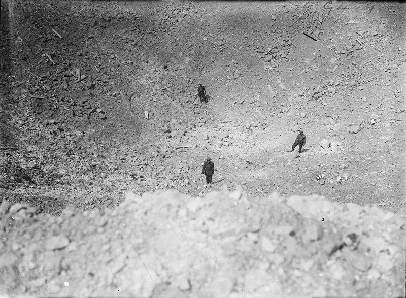
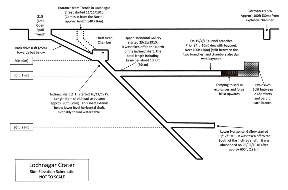
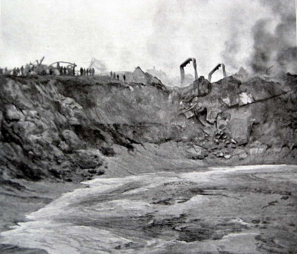